Simple automatic walking transport trolley and application thereof

A technology of automatic walking and transporting trolleys, applied in the direction of transportation and packaging, conveyors, conveyor objects, etc., can solve the problems of engine misalignment, misplaced assembly parts, and staff walking around to pick up materials, etc., to buffer impacts, improve automation, The effect of reducing labor intensity

Pending Publication Date: 2020-03-31
GUANGXI YUCHAI MASCH CO LTD
View PDF0 Cites 0 Cited by
  • Summary
  • Abstract
  • Description
  • Claims
  • Application Information

AI Technical Summary

Problems solved by technology

At present, when ordinary material trolleys are used to manually push and pull materials, it is easy to cause misalignment between a single delivery material trolley at the line and the online engine, causing employees to move around to pick up materials and miss assembly parts, affecting production efficiency and product quality control

Method used


Image

  • Simple automatic walking transport trolley and application thereof
  • Simple automatic walking transport trolley and application thereof
  • Simple automatic walking transport trolley and application thereof

Examples


Embodiment 1

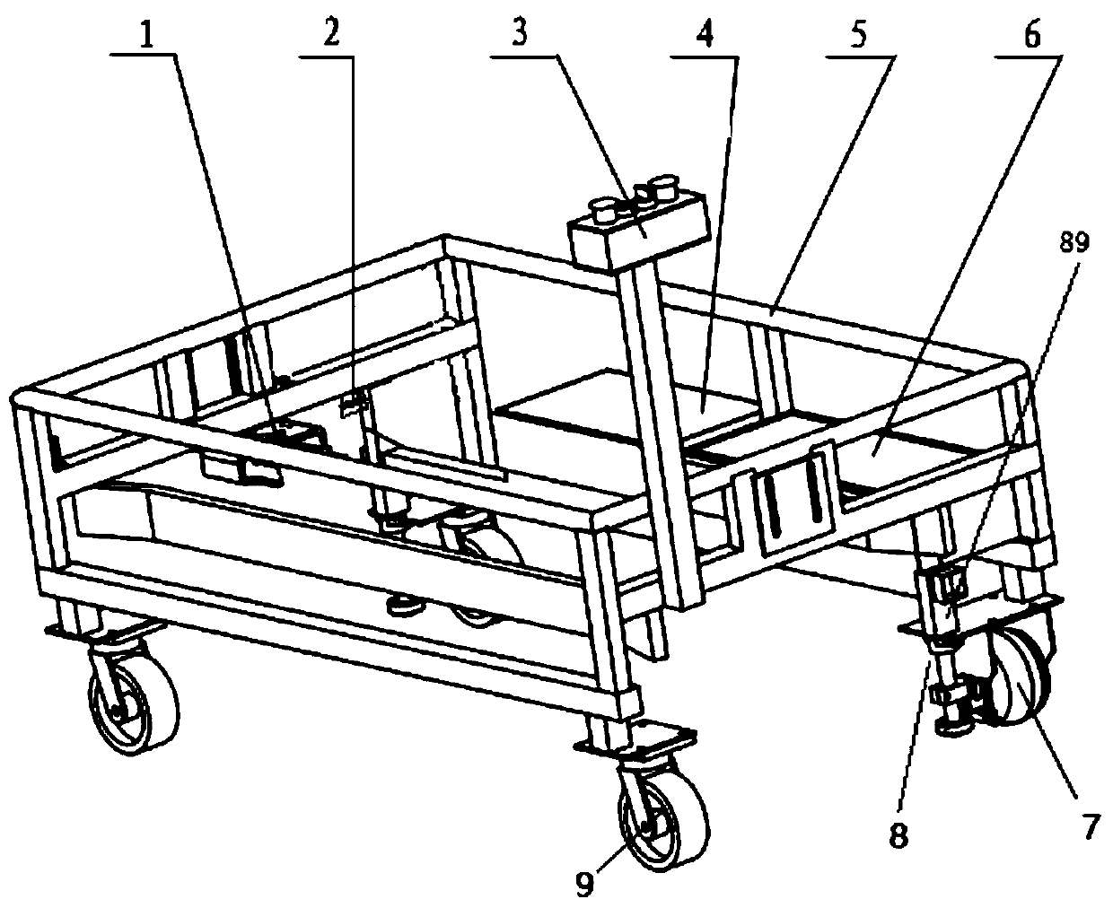
[0034] In this embodiment, the structure of the adjusting guiding device 8 is the same as that of the fixing guiding device. For example, the fixed guiding device includes a second fixed rod, a second bearing, and a second fixed plate; the second fixed rod includes a second cylinder and a second screw, and the second screw is screwed into an adapted first Two nuts. The size and connection relationship of each component are the same as those of the adjustment guide mechanism.

Embodiment 2

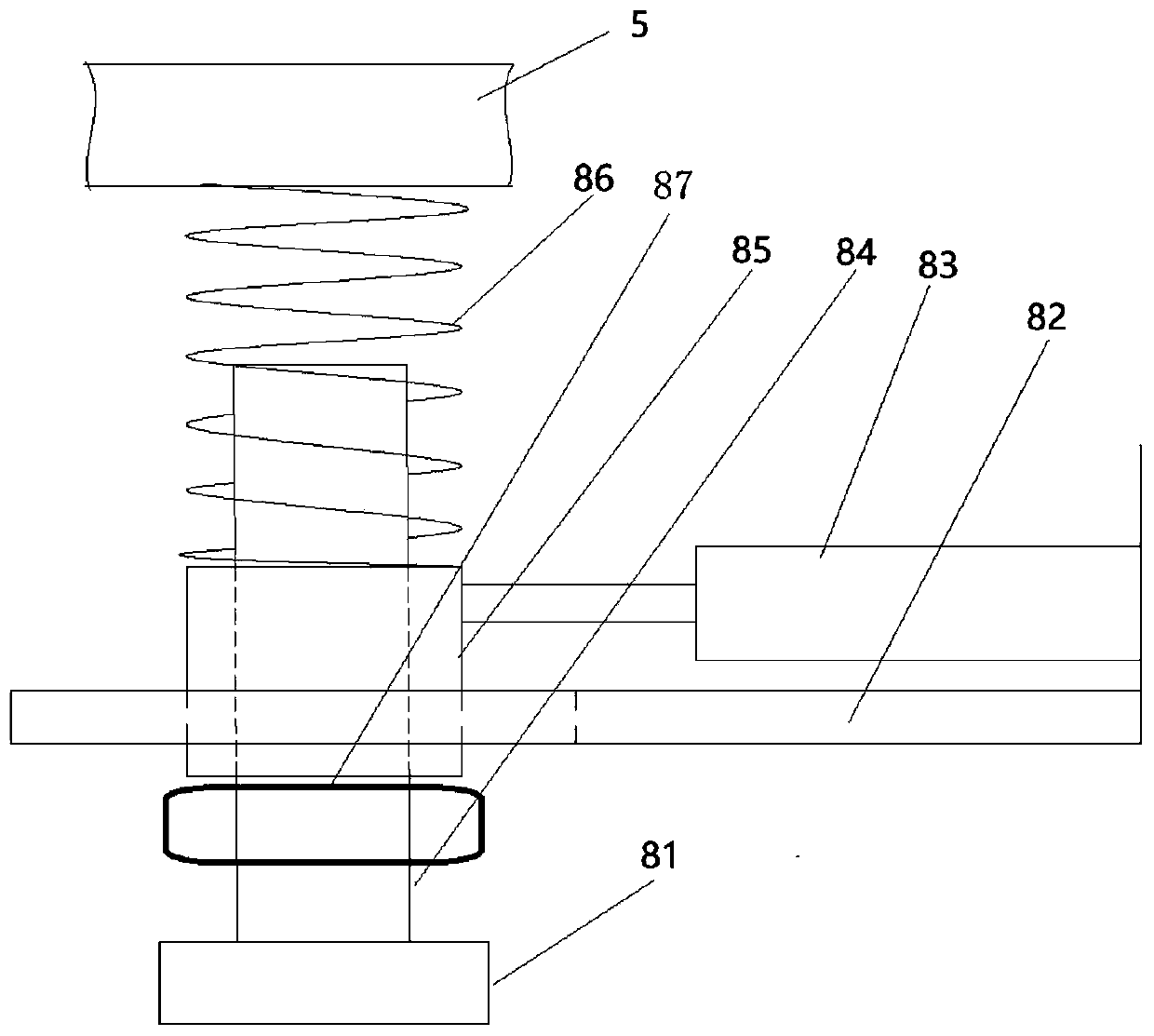
[0036] In Embodiment 1, since the structure of the adjustable guiding device 8 is the same as that of the fixed guiding device, neither of them can adjust the positional relationship during use to obtain a solution that is more beneficial to turning. Therefore, the width of the guide rail groove is generally larger than the diameter of the bearing 81 Only 20-30mm larger can meet the turning requirements of the trolley. If the distance between the bearing 81 and both sides of the guide rail groove is small, the turning angle of the trolley will be reduced; if the distance between the bearing 81 and both sides of the guide rail groove is large, the running process of the trolley will be unstable, and the bearing 81 will hit the inner side of the guide rail groove back and forth, which will intensify The whole car shakes, shaking the parts on the car. For this reason, this embodiment further improves the adjustment guide device 8 arranged at the rear end of the vehicle frame 5 . ...

Embodiment 3

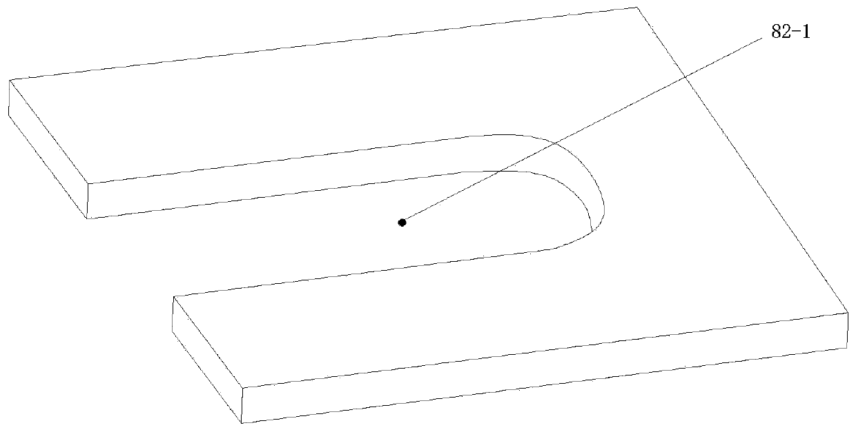
[0040] As a further improvement to Embodiment 2, when using the bearing 81 as a guide for guiding, the bearing 81 must be in a horizontal state. If the fixed rod 89 or the screw rod 81 or other parts are hit, the bearing 81 is inclined upward or downward, causing the bearing 81 to be in a horizontal state. When contacting the side wall of the guide rail groove, upward or downward separation will occur, which not only affects the guiding ability of the bearing 81, but also affects the forward speed of the trolley. Therefore, design a kind of guide wheel of rolling ball type to replace bearing 81 as guide member. Specific reference Figure 4-5 , The guide wheel includes a base 14 , an iron ball 10 , and a limiting device, and the top surface of the base 14 is welded to the lower end of the screw rod 81 . The base 14 is a block body, and U-shaped grooves 15 are provided on its two opposite end faces, so that the base 14 is in the shape of an "I". Two ends of the base 14 are pro...


PUM


Abstract

The invention discloses a simple automatic walking transport trolley and an application thereof. The transport trolley comprises a frame, rollers, an inductive switch, a power supply and a control system, wherein the rollers are mounted at the bottom of the frame, the inductive switch is fixed at a front end of the frame, the control system comprises a controller, a servo motor and a starting switch, the controller is used for receiving a signal of the inductive switch and further used for controlling the servo motor to start and stop, the starting switch is fixed at a rear end of the frame, afixed guide device is arranged at a front end of the frame, an adjusting guide device is arranged at the rear end of the frame, the distance from the adjusting guide device to the right side of the frame is equal to the distance from the fixed guide device to the right side of the frame, the guide device comprises a fixing rod and a guide piece, an upper end of the fixing rod is fixed to the bottom of the frame, and the guide part is fixed to a lower end of the fixing rod. The transport trolley is advantaged in that the transport trolley is compact in structure, saves raw materials, improvesoperation stability and the like.

Description

technical field [0001] The invention relates to the technical field of vehicles, in particular to a simple self-propelled transport trolley and its application on an engine assembly line. Background technique [0002] The engine will carry out the SPS distribution of materials before assembly, and in order to ensure that the engine and the material trolley can be transferred and assembled one by one during the distribution process, this requires that the distribution of engine materials requires a simple and suitable self-propelled transportation tool. At present, when ordinary material trolleys are used to manually push and pull materials, it is easy to cause misalignment between a single delivery material trolley at the line and the online engine, causing employees to move around to pick up materials and miss assembly parts, affecting production efficiency and product quality control. [0003] The disclosure of the above background technical content is only used to assist ...

Claims


Application Information

Patent Timeline
Patent Type & Authority Applications(China)
IPC IPC(8): B65G35/00B65G43/00
CPCB65G35/00B65G43/00B65G2203/0266
Inventor 范才翼黄雄
Owner GUANGXI YUCHAI MASCH CO LTD
Why Eureka
Try Eureka