
Eccentric crankshaft polishing clamp

An eccentric, crankshaft technology, applied in the direction of grinding workpiece supports, can solve the problems of low processing efficiency and troublesome operation, and achieve the effects of convenient machining, simple structure and low cost

Inactive Publication Date: 2018-01-12
JIANGSU GANGYANG
View PDF0 Cites 0 Cited by
  • Summary
  • Abstract
  • Description
  • Claims
  • Application Information

AI Technical Summary

Problems solved by technology

The existing methods mostly use screws to fix, the operation is quite troublesome and the processing efficiency is low

Method used


Image

  • Eccentric crankshaft polishing clamp
  • Eccentric crankshaft polishing clamp
  • Eccentric crankshaft polishing clamp

Examples


Embodiment Construction

[0015] The preferred embodiments of the present invention will be described in detail below in conjunction with the accompanying drawings, so that the advantages and features of the present invention can be more easily understood by those skilled in the art, and the protection scope of the present invention will be defined more clearly.

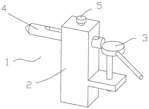
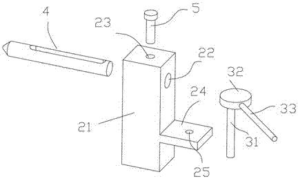
[0016] Such as Figure 1 to Figure 4 As shown, the eccentric crankshaft grinding jig 1 includes a fixed protrusion 2 which includes a columnar longitudinally arranged protrusion body 21, and the top of the protrusion body 21 is provided with a transversely arranged guide circular hole 22 And a longitudinally arranged positioning circular hole 23, the guide circular hole 22 is provided with a clamping rod 4, the positioning circular hole 23 is provided with a positioning screw 5, and the bottom of the convex body 21 is provided with a transversely arranged rotating flange 24. The rotating flange 24 is provided with a flange round hole 25, and a r...


PUM


Abstract

The invention discloses an eccentric crankshaft polishing clamp. The eccentric crankshaft polishing clamp includes a first convex block; the fixing convex block includes a cylindrical convex block body which is longitudinally arranged; a horizontal guiding circular hole and a longitudinal positioning circular hole are formed in the top of the convex block body; a clamping bar is arranged in the guiding circular hole; a positioning screw is arranged in the positioning circular hole; a horizontal rotation flange is arranged on the bottom of the convex block body; a flange circular hole is formedin the rotation flange; a rotatable clamping support is arranged in the flange circular hole; the clamping support includes a rotatable shaft rod; the top of the rotatable shaft rod is eccentricallyprovided with a clamping disc; and a handle is arranged on a side wall of the clamping disc. A user places a crankshaft on the top of the clamping bar, operates the handle, and allows the clamping disc to rotate, the clamping disc clamps the tail of the clamping bar so as to allow the clamping bar to move forward, and the crankshaft is pushed so as to facilitate later machining.

Description

Technical field [0001] The invention relates to a crankshaft processing equipment, more specifically, an eccentric crankshaft grinding fixture. Background technique [0002] The crankshaft is a common mechanical transmission part, which is usually formed gradually by castings and then processed by machining later. When processing, the crankshaft needs to be fixed. The existing methods mostly adopt screw fixation, which is troublesome in operation and low in processing efficiency. Summary of the invention [0003] The invention mainly solves the technical problems existing in the prior art, thereby providing an eccentric crankshaft grinding fixture. [0004] The above technical problems of the present invention are mainly solved by the following technical solutions: [0005] An eccentric crankshaft grinding fixture, characterized in that the eccentric crankshaft grinding fixture comprises a fixed projection, the fixed projection comprises a columnar longitudinally arranged projectio...

Claims


Application Information

Patent Timeline
Patent Type & Authority Applications(China)
IPC IPC(8): B24B41/06
Inventor 刘金芳孙小雨
Owner JIANGSU GANGYANG
Learn More