Ceramic closestool equipped with sunken hidden water tank without motor drive

A motor-driven, hidden technology, applied in flushing toilets, water supply devices, buildings, etc., can solve the problems of affecting the sewage discharge effect of the toilet, the pressure of the toilet sewage, and affecting the safety of use, etc., to ensure the sewage effect and cleanliness. , the effect of ensuring stability

Inactive Publication Date: 2020-03-31
陈慕生 +1
View PDF7 Cites 0 Cited by
  • Summary
  • Abstract
  • Description
  • Claims
  • Application Information

AI Technical Summary

Problems solved by technology

[0003] In order to solve the above-mentioned technical problems, the present invention provides a ceramic toilet equipped with a sinking hidden water tank that does not need to be driven by a motor and uses external tap water pressure to wash, so as to solve the existing similar sinking hidden water tank ceramic toilets. Water pumps or external tap water pressure are mostly used for scrubbing, controlled by electric drain valves, to flush the excrement inside the toilet. When installing and using ceramic toilets, additional sockets need to be installed to meet the needs of power supply or external water pressure requirements, which is not only cumbersome, but also easy. Instability such as electric leakage and low external water pressure, which cannot be flushed, affects the safety of use, and the sewage discharge pressure inside the toilet is weak, and excrement cannot be discharged from the toilet quickly and effectively, which is likely to affect the sewage discharge effect inside the toilet

Method used


Image

  • Ceramic closestool equipped with sunken hidden water tank without motor drive
  • Ceramic closestool equipped with sunken hidden water tank without motor drive
  • Ceramic closestool equipped with sunken hidden water tank without motor drive

Examples


Embodiment

[0028] as attached figure 1 to attach Figure 8 Shown:

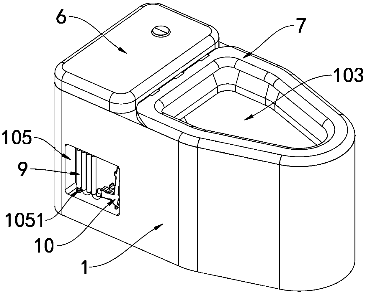
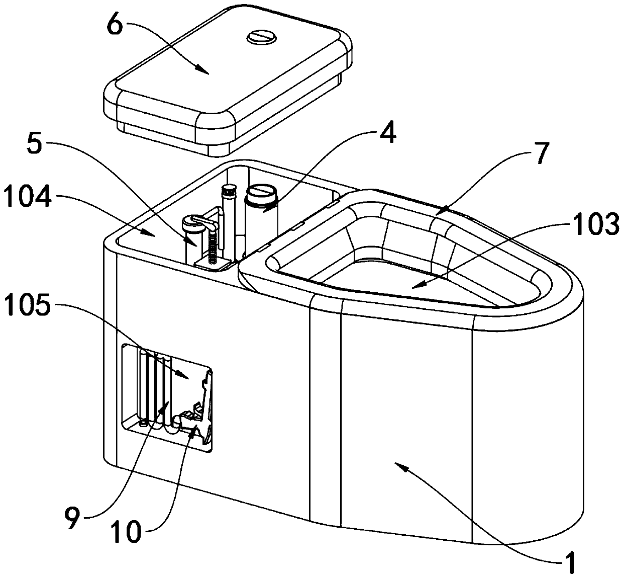
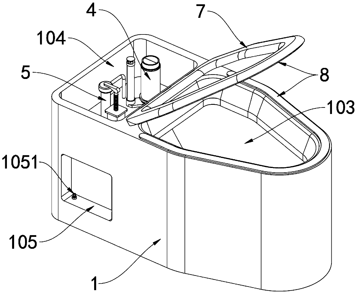
[0029] The invention provides a ceramic toilet equipped with a sinking hidden water tank without motor drive, including a toilet body 1, an upper drain pipe 2, a drain valve 4, a water inlet valve 5, a toilet ring 7, a flexible cleaning pipe 9 and a spray gun 10; The top of the main body 1 is provided with an upper drainage ring 101 in a circular shape, and a sewage pipe 102 is provided at the bottom of the toilet main body 1; The water end is connected; a water tank tank 104 is arranged in the top of the rear end of the toilet main body 1, and the volume of the water tank tank 104 is 4L. 1041, and the bottom of the drain valve 4 is installed at the drain port 1041, which can reduce the height of the matching water tank of the toilet main body 1, so that the water tank sinks and hides in the bottom of the toilet main body 1, so as to ensure the aesthetic feeling of the toilet main body 1; The bottom is provided with a...


PUM


Abstract

The invention provides a ceramic closestool equipped with a sunken hidden water tank without motor drive, and relates to the technical field of closestools. The closetool comprises a closetool main body, an upper drain pipe and a lower drain pipe. An upper drainage loop is formed in the top of the closestool main body in a surrounding manner, and a blow-off pipe is arranged at the bottom of the closestool main body; a defecation groove is formed in the front end of the closestool main body, and the bottom of the defecation groove is communicated with the water inlet end of the blow-off pipe; awater outlet and a water inlet are respectively formed in the bottom of the water tank groove in the rear end of the closestool main body, and the bottom of the water inlet valve is mounted at the water inlet; the upper drainage pipe is mounted in the closestool main body. According to the invention, the water flow in the water tank groove can flow into the upper drainage loop through the upper drain pipe under the influence of water pressure; water flow is sprayed out through an upper drain hole formed in the upper drainage loop, so the inner wall of the toilet bowl is flushed, and the problem that a traditional hidden (sunken) water tank toilet bowl adopts a water pump to supply water and adopts an electric drainage valve to control, and installation and wiring are tedious is solved.

Description

technical field [0001] The invention belongs to the technical field of toilets, and more specifically relates to a ceramic toilet equipped with a sinking hidden water tank without being driven by a motor. Background technique [0002] The toilet is an indispensable part of people's life, and the flush toilet has been widely used in the toilets of families, hotels, and office buildings with advantages such as comfort and appearance; the ceramic toilet can refer to the CN104047350A patent, which mainly includes a siphon toilet seat, and the siphon toilet seat It includes a water inlet, a spray channel, a seat ring, a siphon pipe and a sewage outlet, the water inlet connects the water tank with the beginning of the spray channel; the cleaning surface is provided with steps, and the steps are arranged on the cleaning The middle part of one end connected with the sewage inlet, the height of the steps is 1-5cm, the distance between the steps and the sewage inlet is 7-18cm, the cov...

Claims


Application Information

Patent Timeline
IPC IPC(8): E03D11/06E03D11/13
CPCE03D11/06E03D11/13
Inventor 陈慕生蔡文浩
Owner 陈慕生
Why Eureka
Try Eureka