
Rigid-flexible coupling rotating platform

A rotating platform, rigid-flexible coupling technology, applied in the direction of instruments, computer control, simulators, etc., can solve the problems of complex compensation control methods, difficult friction model, poor effect, etc., to simplify the compensation control method, use The effect of low cost and high rotation positioning accuracy

Inactive Publication Date: 2020-03-31
GUANGDONG UNIV OF TECH
View PDF9 Cites 2 Cited by
  • Summary
  • Abstract
  • Description
  • Claims
  • Application Information

AI Technical Summary

Problems solved by technology

However, the existing technology has poor effects on reducing its positioning accuracy, and there are obvious shortcomings: a. It is difficult to establish a highly accurate friction model; b. The method of compensation control is very complicated; c. The use of frictionless and low Frictional kinematic pairs are more costly to implement

Method used


Image

  • Rigid-flexible coupling rotating platform
  • Rigid-flexible coupling rotating platform
  • Rigid-flexible coupling rotating platform

Examples


Embodiment Construction

[0029] The accompanying drawings are for illustrative purposes only, and should not be construed as limitations on this patent; in order to better illustrate this embodiment, certain components in the accompanying drawings will be omitted, enlarged or reduced, and do not represent the size of the actual product; for those skilled in the art It is understandable that some well-known structures and descriptions thereof may be omitted in the drawings. The positional relationship described in the drawings is for illustrative purposes only, and should not be construed as a limitation on this patent.

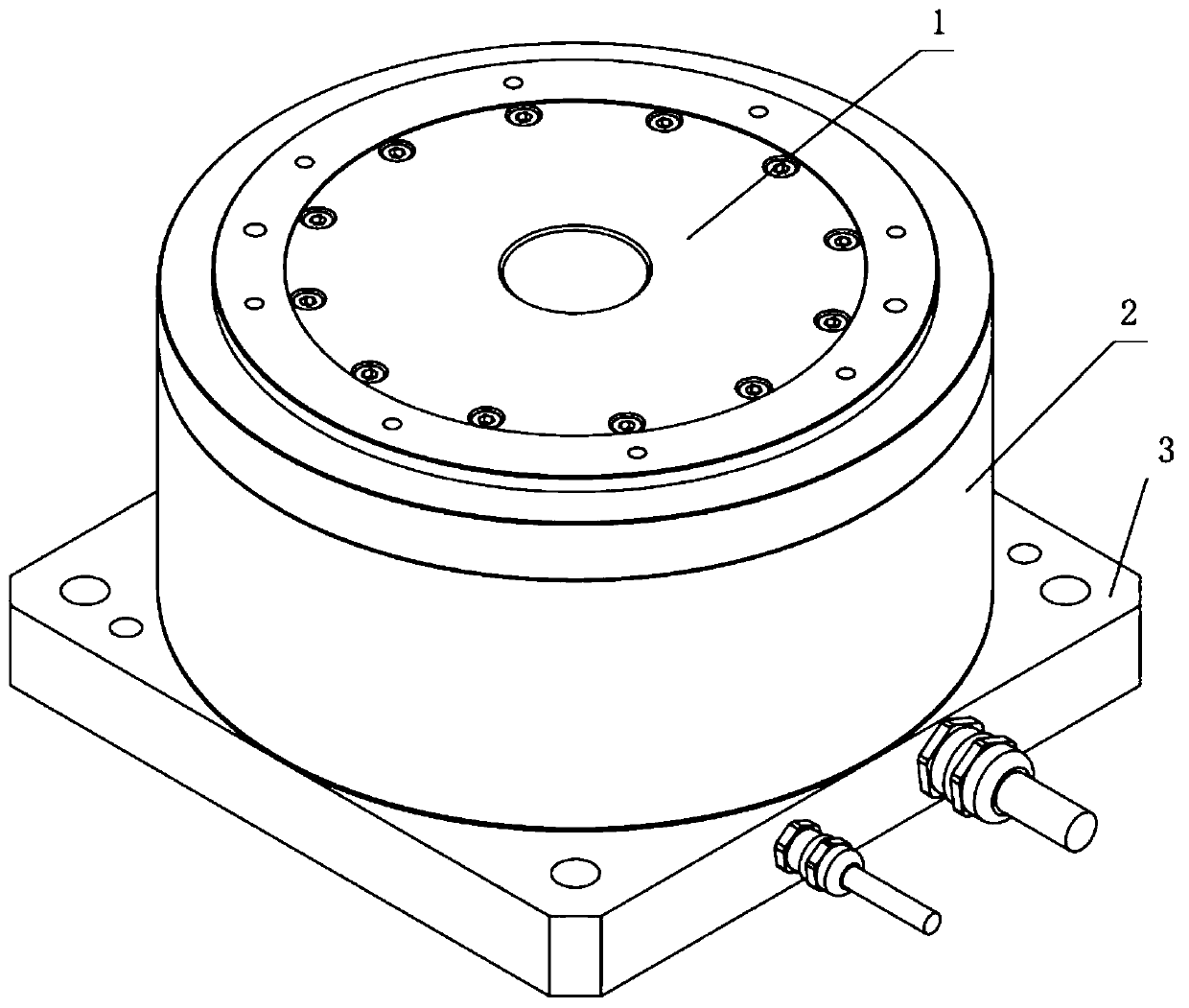
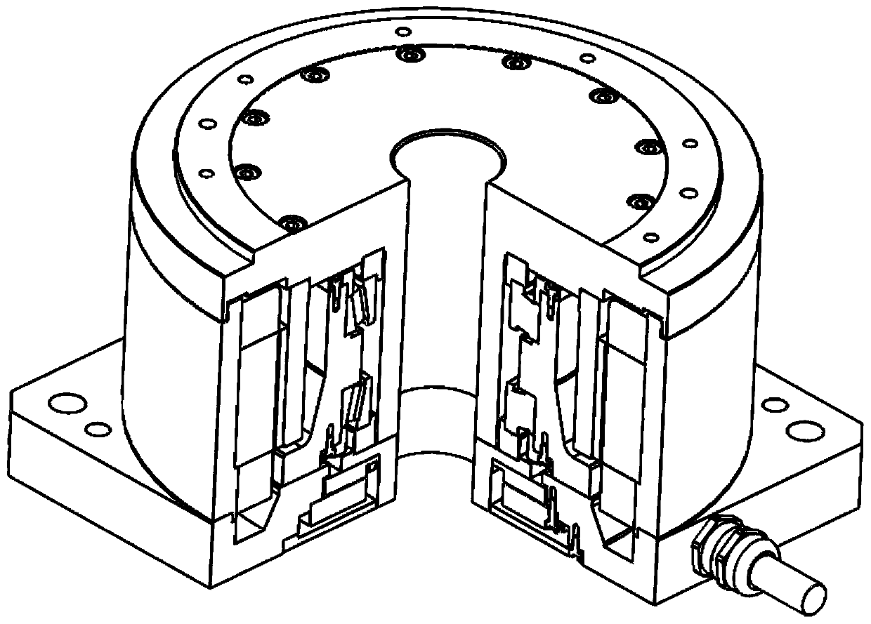
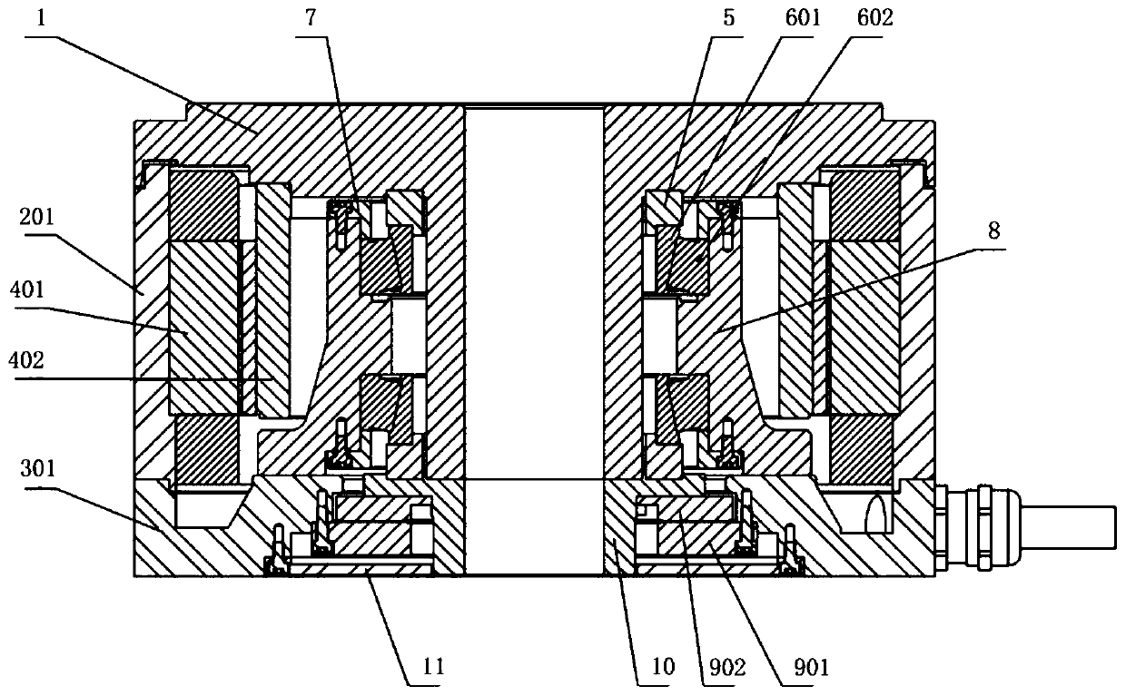
[0030] Such as figure 1 As shown, the rigid-flexible coupling rotating platform proposed by the present invention includes: a chassis (3), a core rotating platform (1) and a rotating body (2). Such as figure 2 , 3 As shown, the rotating body (2) includes: a rotating driver (4), a composite rotating flexible hinge ring (5), a rigid bearing (6), a bearing sleeve (8), and a retaining...


PUM


Abstract

The invention discloses a rigid-flexible coupling rotating platform. The rigid-flexible coupling rotating platform comprises a machine base, a rigid bearing, a bearing sleeve, a core rotating platform, a rotating driver and a composite rotating flexible hinge ring. The bearing sleeve is fixed to the machine base. The rigid bearing is connected with the core rotating platform through the compositerotating flexible hinge ring kinematic pair. The rigid bearing is connected with the machine base through the bearing sleeve. The rotary driver is used for driving the core rotary platform to rotate.When the rotary driver applies driving force to the core rotary platform to enable the core rotary platform to rotate, the driving force can enable the composite rotary flexible hinge ring to generateelastic deformation. According to the rigid-flexible coupling rotating platform, the friction dead zone is overcome and the rotation is compensated by utilizing the elastic deformation of the composite flexible hinge ring, a highly accurate friction force model does not need to be utilized, and a compensation control method is simplified.

Description

technical field [0001] The present invention relates to the technical field of rotating platforms, and more particularly, to a rigid-flexible coupling rotating platform. Background technique [0002] Rotary platforms are widely used in modern industrial fields. Uncertain changes in surface roughness between kinematic pairs in a rotating platform can lead to uncertain changes in the magnitude of frictional resistance. However, during the start, stop and micro-rotation process of the rotating platform, the speed of the rotating platform is relatively low, and the amplitude fluctuation of the above-mentioned frictional resistance may easily lead to the "crawling" phenomenon of the rotating platform. Under the action of the closed-loop control system, the driver will overcome the frictional resistance by increasing the driving force and compensate the positioning error of the rotating platform. During the above compensation process, the rotating platform will experience freque...

Claims


Application Information

Patent Timeline
Patent Type & Authority Applications(China)
IPC IPC(8): G05B19/4093
CPCG05B19/40937G05B2219/32161
Inventor 危宇泰杨志军黄建彬高忠义黄观新白有盾
Owner GUANGDONG UNIV OF TECH
Learn More