A rigid-flexible coupling vibrating mirror motor and its control method

A rigid-flexible coupling and vibrating mirror motor technology, which is applied in the direction of AC motor angular single-axis angular velocity control, control of mechanical energy, estimation/correction of motor parameters, etc., can solve the complex compensation control method of the rotation control system, which is difficult to establish highly accurate The friction model, the difference of the microscopic characteristics of the contact surface, etc., achieve the effects of reducing the complexity of control, easy observation and compensation, and low cost of use

Active Publication Date: 2021-10-19
GUANGDONG UNIV OF TECH
View PDF3 Cites 0 Cited by
  • Summary
  • Abstract
  • Description
  • Claims
  • Application Information

AI Technical Summary

Problems solved by technology

[0006] Due to the differences in the microscopic characteristics of the contact surface between the kinematic pairs and manufacturing errors, it is difficult to establish a highly accurate friction model, resulting in the need for complex compensation control methods in the rotation control system
[0007] Low-friction kinematic pairs such as air bearings or magnetic bearings are expensive to implement, limiting their use

Method used


Image

  • A rigid-flexible coupling vibrating mirror motor and its control method
  • A rigid-flexible coupling vibrating mirror motor and its control method
  • A rigid-flexible coupling vibrating mirror motor and its control method

Examples


Embodiment Construction

[0047] The accompanying drawings are for illustrative purposes only, and should not be construed as limitations on this patent; in order to better illustrate this embodiment, certain components in the accompanying drawings will be omitted, enlarged or reduced, and do not represent the size of the actual product; for those skilled in the art It is understandable that some well-known structures and descriptions thereof may be omitted in the drawings. The positional relationship described in the drawings is for illustrative purposes only, and should not be construed as a limitation on this patent.

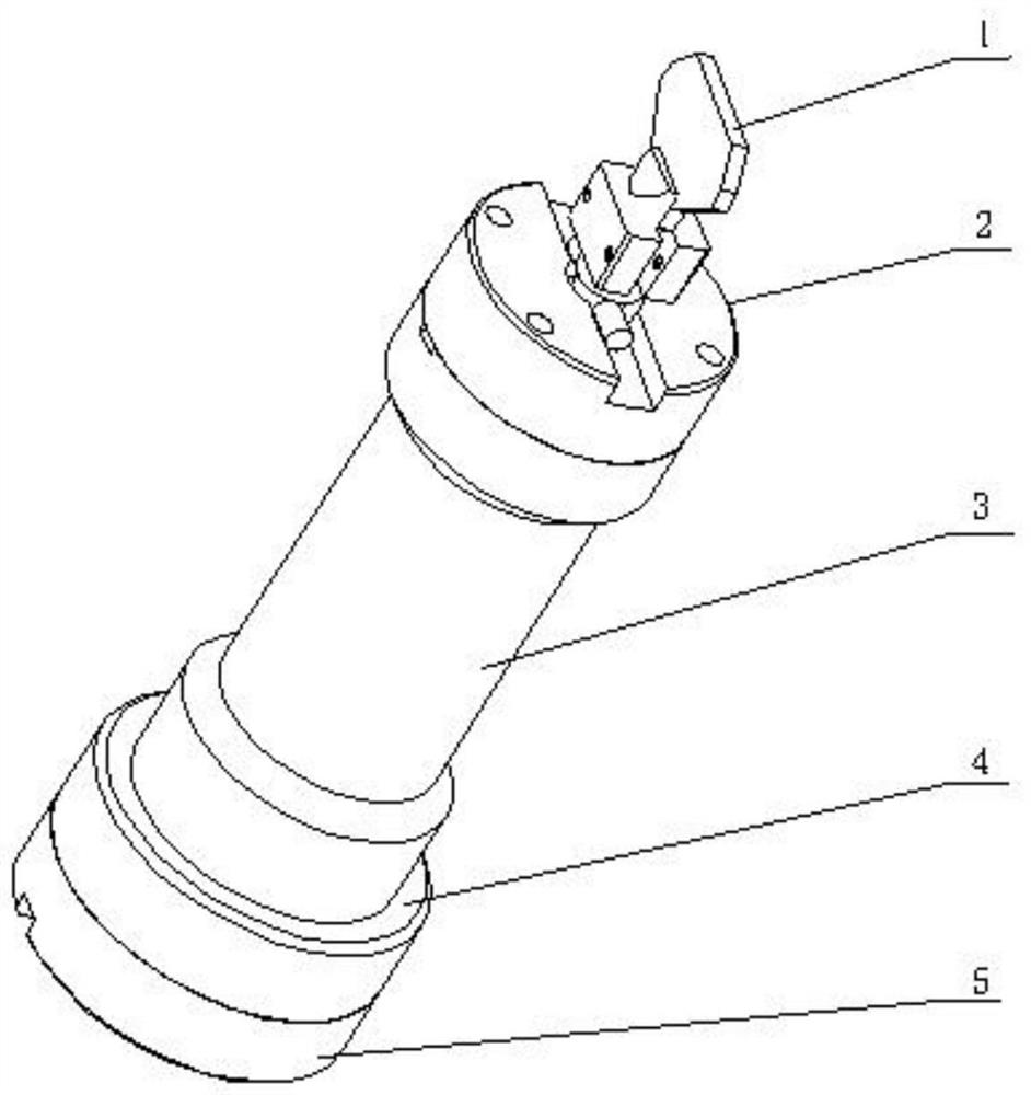
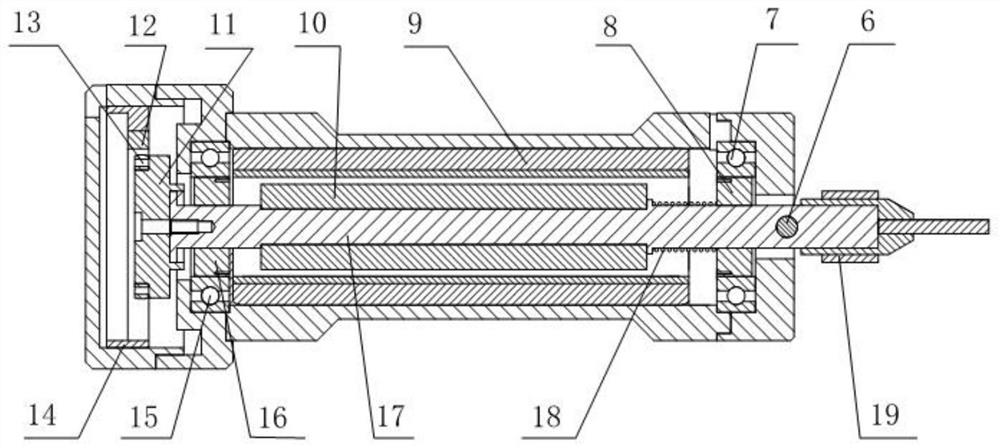
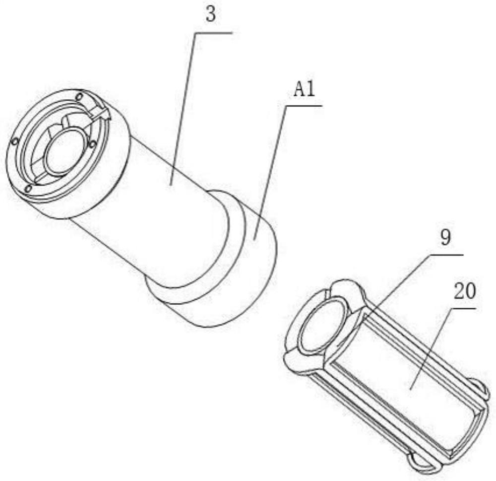
[0048] Such as figure 1 , 2As shown, the rigid-flexible coupling vibrating mirror motor proposed by the present invention includes: vibrating mirror lens (1), stator (A1), rotor (B1) rotating relative to the stator, bearing blocks (2, 4), jacket (19) and a grating encoder for feedback of the rotational position of the rotor (B1). Among them, such as image 3 As shown, the stator (...


PUM


Abstract

The invention relates to a rigid-flexible coupling vibrating mirror motor and a control method thereof. The rigid-flexible coupling vibrating mirror motor includes: a stator, a rotor rotating relative to the stator, a bearing seat and a grating encoder; the rotor includes: a rotating shaft , a rigid-flexible coupling bearing and a plurality of magnets; the rigid-flexible coupling bearing is installed on the rotating shaft; the bearing seat positions the rotor in the stator through the rigid-flexible coupling bearing; the rigid-flexible coupling The bearing includes: a rigid bearing and a flexible hinge ring capable of elastic deformation, the flexible hinge ring is fixed in the inner ring of the rigid bearing; the grating encoder is used to measure the angular displacement of the rotating shaft. The invention utilizes the elastic deformation of the flexible hinge ring to overcome the frictional dead zone, and uses the state observer ESO to estimate the disturbance information during the motor movement process. Through the rigid-flexible coupling design, the disturbance bandwidth of the ESO is reduced, and the active disturbance rejection control is improved. The performance improves the control precision.

Description

technical field [0001] The present invention relates to the technical field of vibrating mirror motors, and more specifically, to a rigid-flexible coupling vibrating mirror motor and a control method thereof. Background technique [0002] The galvanometer motor is a special swing motor, which is widely used in laser marking, laser engraving, laser drilling, stage lighting control, etc. Uncertain changes in the surface roughness between the moving pairs in the vibrating mirror motor will lead to uncertain changes in the magnitude of the frictional resistance, and during the start, stop and micro-feeding of the motor rotor, the speed of the motor rotor is relatively low, the above The amplitude fluctuation of frictional resistance can easily lead to the "crawling" phenomenon of the motion platform. Under the action of the closed-loop control system, the driver will increase the driving force to overcome the frictional resistance and compensate the positioning error of the vib...

Claims


Application Information

Patent Timeline
Patent Type & Authority Patents(China)
IPC IPC(8): H02K7/10H02K7/08H02K11/22H02P23/14H02P23/18
CPCH02K7/08H02K7/10H02P23/14H02K11/22H02P23/18
Inventor 韦胜强杨志军彭皓白有盾黄观新
Owner GUANGDONG UNIV OF TECH
Why Eureka
Try Eureka