Input device and image forming apparatus
An input device and image technology, applied in image communication, data processing input/output process, pulse technology, etc., can solve problems such as difficult vibration state control, unevenness, etc.
- Summary
- Abstract
- Description
- Claims
- Application Information
AI Technical Summary
Problems solved by technology
Method used
Image

Examples
no. 1 approach example
[0035] refer to Figure 1 to Figure 7 A first embodiment example of the present invention will be described.
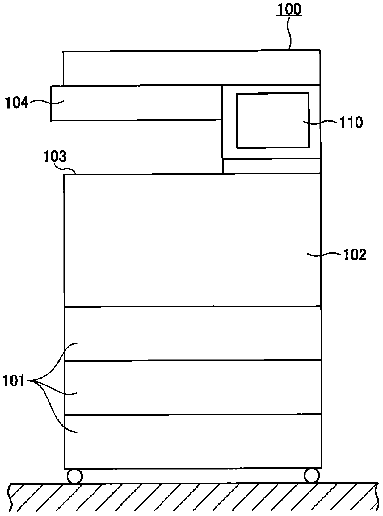
[0036] figure 1 An example of the image forming apparatus 100 of this embodiment example is shown.
[0037] The image forming apparatus 100 of the present embodiment is a digital multifunction peripheral called an MFP (MultiFunction Peripheral).
[0038] The image forming apparatus 100 includes a paper cassette 101 , an image forming unit 102 , a paper discharge unit 103 , a document reading unit 104 , and an operation panel unit 110 .
[0039] The image forming unit 102 performs image forming processing for forming an image of a document read by the document reading unit 104 or a document conveyed from outside on the front or back of the paper conveyed from the paper cassette 101 .
[0040] The paper on which an image has been formed in the image forming unit 102 is discharged from the paper discharge unit 103 .
[0041] The operation panel unit 110 is an operati...
no. 2 approach example
[0083] Next, refer to Figure 8 A second embodiment example of the present invention will be described.
[0084] In this embodiment example, the attachment state of the vibration element 115 to the operation panel unit 110 of the image forming apparatus 100 is different from that of the first embodiment example. The configuration of the operation panel portion 110 other than the mounting configuration of the vibrating element 115 , the control for vibrating the vibrating element 115 , and the like are the same as those of the first embodiment described above.
[0085] Figure 8 It is a cross-sectional view of the operation panel unit 110 of the present embodiment.
[0086] Figure 8 In the illustrated operation panel unit 110 , a touch panel 118 and a liquid crystal display panel 119 are arranged on the operation panel holding frame 108 . Further, the vibrating element 115 is attached below (inner side) the operation panel holding frame 108 through the position adjustment ...
no. 3 approach example
[0095] Next, refer to Figure 9 ~ Figure 10 A third embodiment of the present invention will be described.
[0096] In the previously described second embodiment, the installation position of the vibrating element 115 is adjusted by the position adjusting part 140 , but in the third embodiment, the center of gravity position adjusting part different from that of the vibrating element 115 is provided. Embodiment examples are different. The configuration of the operation panel unit 110 other than the center-of-gravity position adjustment unit, the control for vibrating the vibrating element 115 , and the like are the same as those of the first embodiment described above.
[0097] Figure 9 It is a cross-sectional view of the operation panel unit 110 of the present embodiment.
[0098] right Figure 9 In the illustrated operation panel unit 110 , a touch panel 118 and a liquid crystal display panel 119 are disposed on the operation panel holding frame 108 . Furthermore, the ...
PUM
 Abstract
Description
Claims
Application Information
 - R&D
- Intellectual Property
- Life Sciences
- Materials
- Tech Scout
- Unparalleled Data Quality
- Higher Quality Content
- 60% Fewer Hallucinations
Browse by: Latest US Patents, China's latest patents, Technical Efficacy Thesaurus, Application Domain, Technology Topic, Popular Technical Reports.
© 2025 PatSnap. All rights reserved.Legal|Privacy policy|Modern Slavery Act Transparency Statement|Sitemap|About US| Contact US: help@patsnap.com