
Power signal detection equipment convenient to overhaul

A power signal, convenient maintenance technology, applied in the direction of electrical equipment structural parts, electrical equipment shell/cabinet/drawer, lighting and heating equipment, etc., can solve problems such as reducing the practical value of testing equipment, equipment damage, etc., to improve convenience , The effect of facilitating maintenance and reducing the time required for maintenance

Inactive Publication Date: 2020-03-31
STATE GRID CORP OF CHINA +3
View PDF6 Cites 2 Cited by
  • Summary
  • Abstract
  • Description
  • Claims
  • Application Information

AI Technical Summary

Problems solved by technology

[0003] The existing power signal detection equipment is generally fixedly connected in the installation box, which leads to the need to remove the detection equipment from the installation box when performing maintenance on the power signal detection equipment, which increases the time spent on maintenance. It is easy to cause equipment damage during the process, thereby reducing the practical value of the detection equipment

Method used


Image

  • Power signal detection equipment convenient to overhaul
  • Power signal detection equipment convenient to overhaul
  • Power signal detection equipment convenient to overhaul

Examples


Embodiment 1

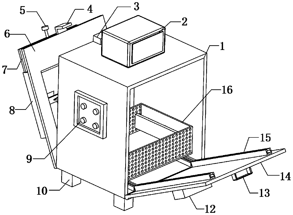
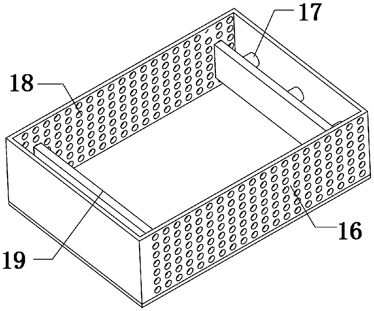
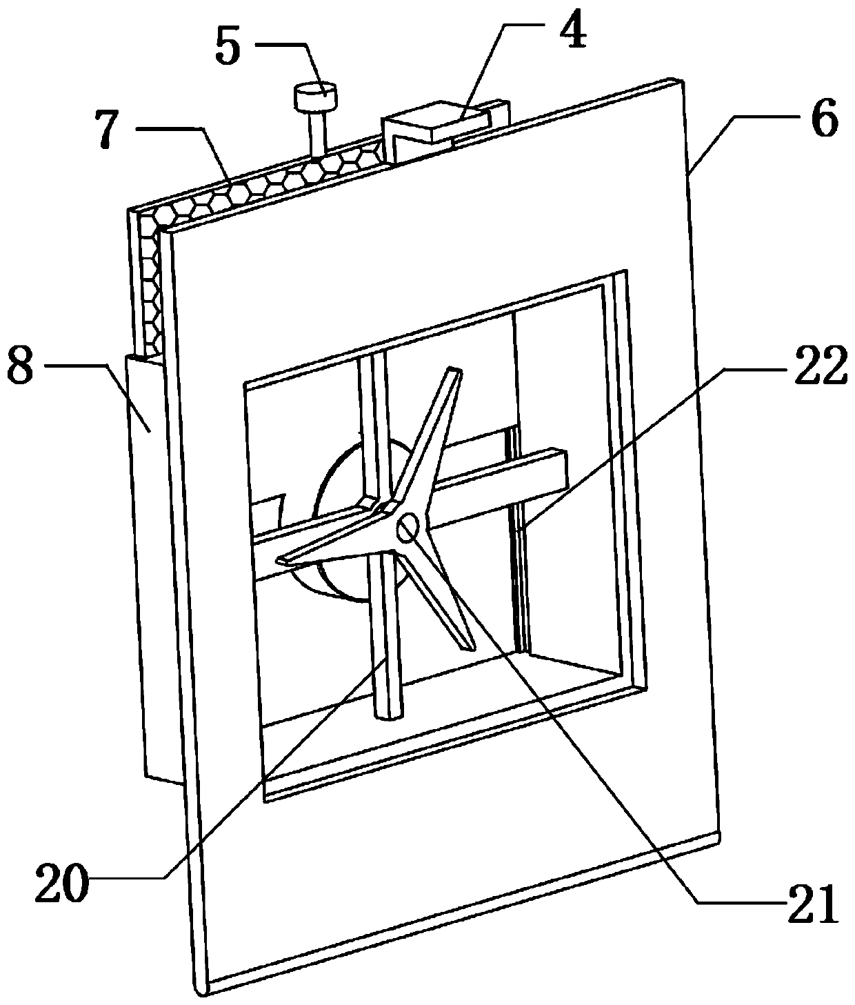
[0029] refer to Figure 1-4 , a power signal detection device for easy maintenance, including an installation box 1, both ends of the bottom inner wall of the installation box 1 are fixed with chute 25 by screws, and the inner walls of the two chute 25 are slidably connected with sliders 24, the two The top outer wall of each slider 24 is fixed with the same storage frame 16 by screws, and the inner walls on both sides of the storage frame 16 are fixed with two hydraulic rods 17 by screws, and the other ends of the two hydraulic rods 17 on one side are fixedly connected. There is the same fixed plate 19, four hydraulic rods 17 are connected with a synchronous hydraulic system, and the outer walls of both sides of the storage frame 16 are provided with cooling holes 18 at equal distances, through which a chute 25 and a slider 24 are provided, and the storage frame 16 passes through the slider. 24 is slidably connected to the inner wall of the chute 25. When installing the testi...

Embodiment 2

[0040] refer to Figure 2-6, a power signal detection device for easy maintenance, including an installation box 1, both ends of the bottom inner wall of the installation box 1 are fixed with chute 25 by screws, and the inner walls of the two chute 25 are slidably connected with sliders 24, the two The top outer wall of each slider 24 is fixed with the same storage frame 16 by screws, and the inner walls on both sides of the storage frame 16 are fixed with two hydraulic rods 17 by screws, and the other ends of the two hydraulic rods 17 on one side are fixedly connected. There is the same fixed plate 19, four hydraulic rods 17 are connected with a synchronous hydraulic system, and the outer walls of both sides of the storage frame 16 are provided with cooling holes 18 at equal distances, through which a chute 25 and a slider 24 are provided, and the storage frame 16 passes through the slider. 24 is slidably connected to the inner wall of the chute 25. When installing the testin...


PUM


Abstract

The invention belongs to the technical field of electric power engineering. The invention relates to detection equipment, in particular to power signal detection equipment convenient to overhaul. Aiming at solving the problems that the existing power signal detection equipment is generally placed in a mounting box, so that when the power signal detection equipment is overhauled, the detection equipment needs to be detached from the mounting box, the overhauling time is prolonged, and the practical value of the detection equipment is reduced, the following scheme is provided, and the mounting box is included. According to the invention, the chute and the slide block are arranged; the storage frame is slidably connected to the inner wall of the sliding groove through a sliding block. Detection equipment installation, when the detection equipment is overhauled, the box door is opened, the storage box slides out of the mounting box, and the sliding block slides to the auxiliary groove, sothat a worker can overhaul the storage box conveniently, the operation is convenient and efficient, the time required for overhaul is shortened, and the practicability of the device is improved.

Description

technical field [0001] The invention relates to the technical field of electric power engineering, in particular to a power signal detection device which is convenient for maintenance. Background technique [0002] Electric power engineering refers to projects related to the transmission and distribution of produced electric energy, and also includes projects that use electric energy as power and energy in various energy fields; similarly, it can also be understood as power transmission and transformation industry expansion projects, In power engineering, power signal detection equipment is needed to detect power signals. [0003] The existing power signal detection equipment is generally fixedly connected in the installation box, which leads to the need to remove the detection equipment from the installation box when performing maintenance on the power signal detection equipment, which increases the time spent on maintenance. It is easy to cause equipment damage during the...

Claims


Application Information

Patent Timeline
Patent Type & Authority Applications(China)
IPC IPC(8): H05K5/00H05K5/02H05K7/20F21V33/00
CPCF21V33/00H05K5/0004H05K5/0213H05K5/0217H05K7/20136
Inventor 苗志国张认祥贾利刚宋建飞赵培珩王路鹏彭晓伟
Owner STATE GRID CORP OF CHINA
Learn More