Double-fluid nozzle

A dual-fluid nozzle and main body technology, applied in the direction of liquid injection devices, injection devices, chemical instruments and methods, etc., can solve the problems of poor micronization performance and narrow use, and achieve the effect of promoting micronization and reducing liquid deposition

A dual-fluid nozzle and main body technology, applied in the direction of liquid injection devices, injection devices, chemical instruments and methods, etc., can solve the problems of poor micronization performance and narrow use, and achieve the effect of promoting micronization and reducing liquid deposition

CN110944756AInactive Publication Date: 2020-03-31SPRAYING SYST JAPAN

Image

  • Double-fluid nozzle
  • Double-fluid nozzle
  • Double-fluid nozzle

Examples


Embodiment Construction

[0037] Hereinafter, preferred embodiments of the present invention will be described with reference to the drawings, but the present invention is not limited to the illustrated embodiments, and various design changes can be made without departing from the gist of the present invention.

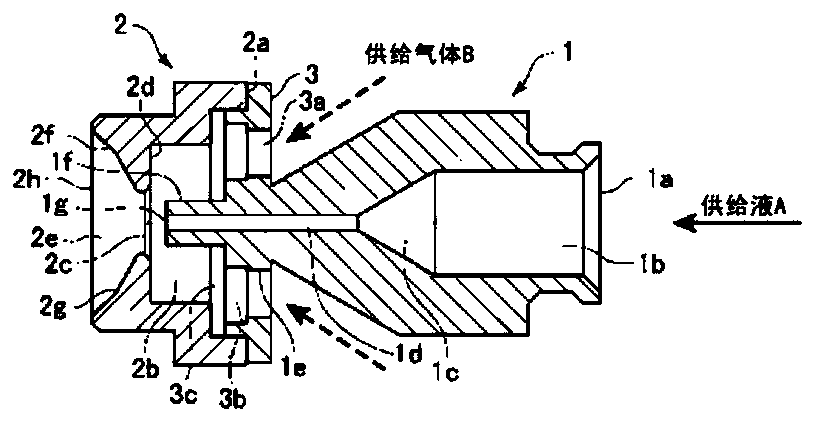
[0038] figure 1 An example of an internal mixing type two-fluid nozzle according to the present invention is shown. The two-fluid nozzle includes a liquid cap (Japanese: liquid cap) main body 1 and an air cap (Japanese: air cap) main body 2 provided on the downstream side tip of the liquid cap main body 1 .

[0039] The liquid cap main body 1 is hollow and opened on the right side in the figure, that is, the upstream side, and serves as a supply port 1a for supplying liquid A such as a mold release agent or an adhesive. Inside the liquid cap main body 1, a first fluid flow path 1b with a uniform inner diameter is formed linearly along the axial direction of the central portion, and a fluid f...


PUM


Abstract

Provided is an internal mixing type double-fluid nozzle which is unlikely to become clogged, is capable of achieving high atomization performance, has a simple configuration, and can used be for various purposes. The double-fluid nozzle is configured to be provided with: a liquid cap body 1 which has a fluid passage formed therein and to which a supply liquid is supplied from the upstream side; and an air cap body 2 which is provided to the downstream section of the liquid cap body 1 and into which a supply gas is supplied, wherein a liquid outlet 1g is provided to the downstream end of the liquid cap body, a gas chamber 2b, into which the supply gas is supplied, is formed in the air cap body 2, a mixed gas outlet 2c is formed on the downstream side of the gas chamber 2b, and a mortar-shaped mixed gas expansion part 2e is provided immediately subsequent to the mixed gas outlet 2c.

Description

technical field [0001] The invention relates to an internal mixing type two-fluid nozzle. Background technique [0002] There are various types of two-fluid nozzles as two-fluid nozzles, and when roughly classified, they include an internal mixing type and an external mixing type. [0003] For the internal mixing type, which mixes the fluid inside the nozzle, it can be atomized efficiently, and it is easy to obtain particles. On the contrary, for the nozzle where the mixed gas is easy to solidify, since the mixed-phase flow is sent inside the nozzle, it is easy to cause clogging. And the disadvantage of being unusable in a short period of time. [0004] On the other hand, the nozzle of the external mixing type has the advantage of being less likely to be clogged because the fluid is mixed in the atmosphere outside the nozzle. Therefore, it can also be used for liquids that are easily solidified, but it has the disadvantages of being poor in micronization performance and na...

Claims


Application Information

Patent Timeline
31 Mar 2020
Publication
CN110944756A
IPC
B05B7/06
CPC
B05B7/0458; B05B15/50; B05B7/06; B05B7/0483; B05B7/066; B01F23/21322
Inventors
滨浦俊一; 关谷宏