Cleaning device for flame cone in atomic absorption spectrometer

A technology of atomic absorption spectroscopy and cleaning equipment, applied in the direction of cleaning methods using tools, cleaning methods using liquids, chemical instruments and methods, etc., can solve the problems of time-consuming and labor-intensive manual scrubbing, decreased absorbance, and failure to work normally. The effect of achieving a good cleaning effect

Inactive Publication Date: 2020-10-16
冯吉
View PDF7 Cites 0 Cited by
  • Summary
  • Abstract
  • Description
  • Claims
  • Application Information

AI Technical Summary

Problems solved by technology

[0002] The flame cone is a built-in part of the atomic absorption spectrometer, also known as the combustion head. The atomic absorption spectrometer is also called the atomic absorption spectrophotometer. The analyte in the sample passes through the flame cone under the flame, decomposes to produce atomic vapor, and the ground state atoms of the element to be measured in the steam are absorbed, and the content of the element to be measured in the sample can be obtained from the degree of weakening of the intensity of the radiated light wave. If the atom is ionized Insufficient, so that the number of atoms in the ground state decreases, the absorbance decreases, and the measured data is inaccurate. The maintenance and maintenance of the flame cone is an important part of instrument maintenance and maintenance. The inner wall of the flame cone needs to be cleaned regularly to prevent it from working normally. At the same time, the inner wall of the flame cone has high requirements for cleaning conditions. Manual scrubbing is too time-consuming and labor-intensive, and other scrubbing methods are not thorough.

Method used


Image

  • Cleaning device for flame cone in atomic absorption spectrometer
  • Cleaning device for flame cone in atomic absorption spectrometer
  • Cleaning device for flame cone in atomic absorption spectrometer

Examples


Embodiment Construction

[0013] In order to make the purpose, technical solutions and advantages of the embodiments of the present invention clearer, the technical solutions in the embodiments of the present invention will be clearly and completely described below in conjunction with the drawings in the embodiments of the present invention. Obviously, the described embodiments It is a part of embodiments of the present invention, but not all embodiments. Based on the embodiments of the present invention, all other embodiments obtained by persons of ordinary skill in the art without creative efforts fall within the protection scope of the present invention.

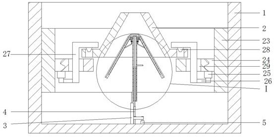
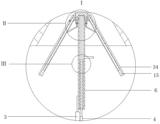
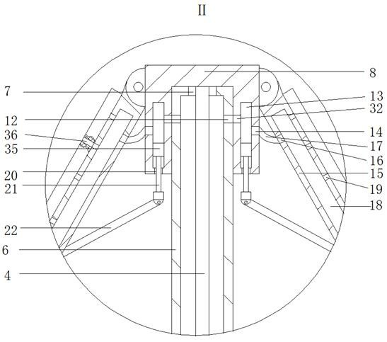
[0014]The cleaning device for the flame cone in the atomic absorption spectrometer, as shown in the figure, includes a cylinder body 1, the inner wall of the cylinder body 1 is fixed with a flame cone 2 through a fixing device, and the first electric telescopic rod is fixedly installed on the inner wall of the bottom of the cylinder body 1 3. The ...


PUM


Abstract

A cleaning device used for a flame cone in an atomic absorption spectrum analyzer comprises a barrel body. The flame cone is fixed to the inner side wall of the barrel body. A first electric telescopic rod, a telescopic shaft and a motor are mounted on the inner wall of the bottom of the barrel body. The first electric telescopic shaft and the motor are located on the left side and the right sideof the telescopic shaft correspondingly. A cleaning agent is pumped into a barrel through a pumping device, meanwhile, an annular piston compresses springs to move downwards, and therefore the pressure intensity in the barrel is larger, and then when second through holes are aligned to third through holes at the next time, the cleaning agent in the barrel can be sprayed out from water spray holesfaster; when the cleaning agent is sprayed from the water spray holes, a certain distance is formed between the cleaning layer and the inner wall of the flame cone, and therefore the cleaning agent achieves stronger flushing and cleaning effects on the inner wall of the flame cone, meanwhile, rectangular plates swing up and down fast, and therefore the inner wall of the flame cone is beaten, and the function of reinforcing the cleaning effect is achieved; and time and labor are saved, and scheduled maintenance of the flame cone is facilitated.

Description

technical field [0001] The invention belongs to the field of cleaning devices for flame cones, in particular to a cleaning device for flame cones in atomic absorption spectrometers. Background technique [0002] The flame cone is a built-in part of the atomic absorption spectrometer, also known as the combustion head. The atomic absorption spectrometer is also called the atomic absorption spectrophotometer. The analyte in the sample passes through the flame cone under the flame, decomposes to produce atomic vapor, the ground state atoms of the element to be measured in the steam are absorbed, and the content of the element to be measured in the sample can be obtained from the degree of weakening of the intensity of the radiated light wave. If the atom is ionized Insufficient, so that the number of atoms in the ground state decreases, the absorbance decreases, and the measured data is inaccurate. The maintenance and maintenance of the flame cone is an important part of instru...

Claims


Application Information

Patent Timeline
Patent Type & Authority Patents(China)
IPC IPC(8): B08B3/02B08B1/00B08B1/04B08B7/02
CPCB08B1/006B08B1/04B08B3/02B08B7/02
Inventor 冯吉王学生易鑫杨明月庞源
Owner 冯吉
Why Eureka
Try Eureka