Large-load actuating cylinder control sliding lock

An actuating cylinder, large load technology, applied in the direction of transmission, chassis, belt/chain/gear, etc., can solve the problem of unable to meet the large load locking, and achieve the effect of reliable retraction and unlocking

Pending Publication Date: 2020-04-03
SICHUAN LINGFENG AVIATION HYDRAULIC MACHINERY
View PDF0 Cites 1 Cited by
  • Summary
  • Abstract
  • Description
  • Claims
  • Application Information

AI Technical Summary

Problems solved by technology

[0003] The purpose of the present invention is to solve the problems existing in the prior art, to provide a slider lock with simple structure, capable of bearing large load, strong locking ability and actuating ability, effectively solving the problem that the structure of conventional electric cylinder lock cannot meet the large load locking The problem

Method used


Image

  • Large-load actuating cylinder control sliding lock
  • Large-load actuating cylinder control sliding lock

Examples


Embodiment Construction

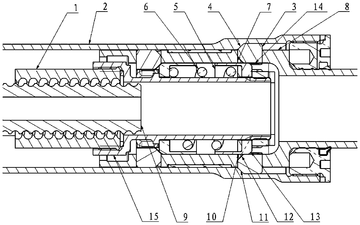
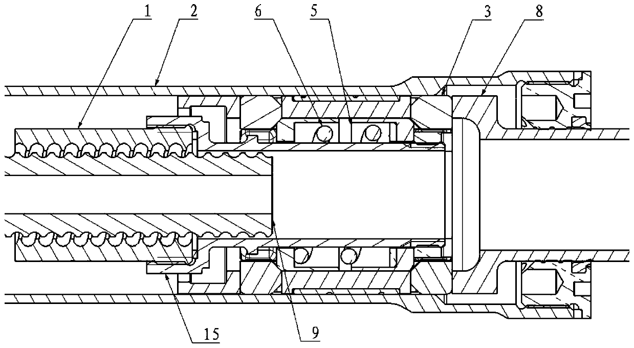
[0012] refer to figure 1 , figure 2 . In the preferred embodiment described below, a large-load actuating cylinder control slip lock includes: assembled in the actuating cylinder, the piston cylinder 2 providing the locking groove and the spring 6 providing the locking force, through the spring sleeve The cylinder 15 is assembled with the lead screw nut 1 and the lead screw 9 in the actuator cylinder, the sliding sleeve 5 assembled on the outer ring surface of the spring sleeve 15, the sliding block 3 radially supported by the sliding sleeve 5, and the guide groove 7 driving the sliding block 3 The moving piston rod 8 is characterized in that: the slider 3 is installed in the guide groove 7 of the piston rod 8, the slider 3 passes through the locking slope 11, leans against the axial locking groove slope 4 of the inner wall of the piston barrel 2 and The outer ring surface 10 of the sliding sleeve 5 is on the tail end surface, and the rear end of the slider 3 abuts against ...


PUM


Abstract

The invention discloses a large-load actuating cylinder control sliding lock, and aims to provide a sliding block lock which is simple in structure, capable of bearing large loads and high in lockingcapacity and actuating capacity.. The sliding block lock is realized through the following technical scheme: a sliding block assembled in the actuating cylinder is installed in a guide groove of the piston rod, the sliding block abuts against the axial locking groove slope of the inner wall of the piston cylinder and the tail end face of the outer ring face through a locking slope, the rear end ofthe sliding block abuts against the end face of the piston rod and slides in the radial direction of the guide face of the guide groove, and a sliding sleeve overcomes spring elastic force through aspring sleeve assembled on the lead screw nut. During locking, the sliding sleeve overcomes the elastic force of the spring through the spring sleeve assembled on the lead screw nut to push the sliding block to move; when the sliding block pushes the conical surface to move to the locking groove inclined surface, the sliding sleeve is pushed by the spring to enable the sliding block to slide outwards in the radial direction of the guide groove guide surface, the tail end face of the outer ring surface of the sliding sleeve moves and abuts against the inner ring surface of the sliding block, external loads cannot enable the sliding block to disengage from a space formed by the piston cylinder, the piston rod guide groove and the sliding sleeve, and locking is achieved. During unlocking, thelead screw nut drives the sliding sleeve through the lead screw to be disengaged from the inner ring face of the sliding block, and unlocking of the sliding block lock is achieved.

Description

technical field [0001] The present invention relates to the locking device applied to the electric retractable actuator of the landing gear, more specifically, the present invention relates to a new type of mechanical locking device capable of bearing a heavy load of more than 3000N. Background technique [0002] As a linear motion actuator, the electric actuator is an energy conversion device used to realize the linear reciprocating motion of the working mechanism or the swing motion of less than 360°. The basic components of a common electric actuator include: motor, gearbox, transmission components, ball screw pair, piston cylinder assembly, piston rod assembly, self-locking assembly, etc. Due to the complex structure of the electric retractable actuator and the reliability of each part is different, different redundancy structure designs will lead to completely different reliability results. Especially the electric actuator with a self-locking device, which can prevent ...

Claims


Application Information

Patent Timeline
Patent Type & Authority Applications(China)
IPC IPC(8): B64C25/26F16H25/24
CPCB64C25/26F16H25/2454
Inventor 匡克焕汪驰郭智
Owner SICHUAN LINGFENG AVIATION HYDRAULIC MACHINERY
Why Eureka
Try Eureka