A method of using a liftable safety guardrail device
A safety guardrail and lifting technology, which is applied in the direction of fences, building materials processing, bridge parts, etc., can solve the problems of increased safety risks at high altitudes, lack of protective measures, and obstacles to the normal use of mechanical equipment, so as to avoid side operations state, safe return to normal altitude, and the effect of reducing safety risks
- Summary
- Abstract
- Description
- Claims
- Application Information
AI Technical Summary
Problems solved by technology
Method used
Image
Examples
Embodiment 1
[0037] see Figure 1 to Figure 5 , the invention discloses a method for using a liftable safety guardrail device, the liftable safety guardrail device comprising: a guardrail arranged between adjacent fixed columns 1 and a guardrail height locking mechanism 4, the guardrail It includes a fixed guardrail 2 and a movable guardrail 3, the movable guardrail 3 is arranged above the fixed guardrail 2, the height of the movable guardrail 3 can be adjusted, and the guardrail height locking mechanism 4 can lock the movable guardrail 3 to the fixed column 1, so that the movable guardrail 3 maintains the required height position, the method comprises the following steps:
[0038] The first step is to install the liftable safety guardrail device on the construction site;
[0039] The second step is to loosen the guardrail height locking mechanism 4, and adjust the height of the movable guardrail 3 as required;
[0040] The third step is to lock the guardrail height locking mechanism 4, an...
Embodiment 2
[0054] see Figure 6 to Figure 7 , the difference between this embodiment and Embodiment 1 is:
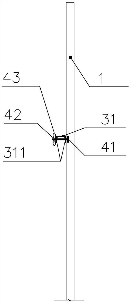
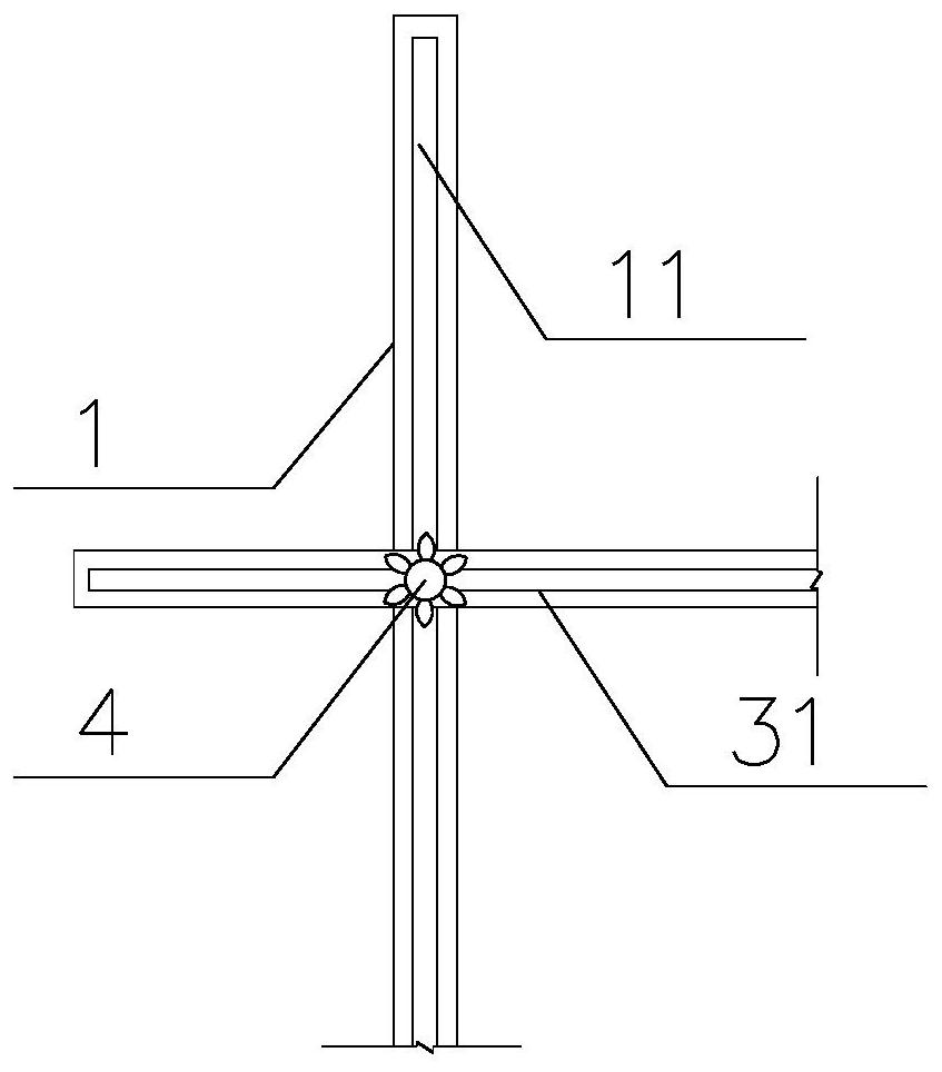
[0055] The height locking mechanism of the guardrail includes a screw mandrel 44, a nut 42 and an anti-rotation block 45. A vertical chute 11 is provided on the fixed column, and a horizontal chute 311 is provided on the upper rail 31 of the movable guardrail. The screw mandrel 44 One end of the screw rod 44 is fixedly connected with the anti-rotation block 45, and the other end of the screw rod 44 passes through the vertical chute 11 of the fixed column 1 and the horizontal chute 311 of the upper rail 31 of the movable guardrail, and then is fixed by the nut 42. , the anti-rotation block 45 is located inside the fixed column 1 , and the fixed column 1 can limit the rotation of the anti-rotation block 45 around the axis of the screw rod 44 inside the fixed column 1 .
[0056] The anti-rotation block, on the one hand, can be used as a limiting device to prevent the screw rod 44 fro...
Embodiment 3
[0061] see Figure 10 , the difference between this embodiment and Embodiment 1 is:
[0062] Described movable guardrail 3 comprises movable guardrail upper gear 31, middle cross bar 34 and several connecting rods 32, and described middle cross bar 34 is positioned between described movable guardrail upper gear 31 and fixed guardrail 2, and described movable guardrail upper gear 31 Between the middle cross bar 34 and between the fixed guardrail 2 and the middle cross bar 34, several parallel connecting rods 32 are respectively arranged in a hinged manner, and the upper and lower adjacent connecting rods 32 are hinged at the same place of the middle cross bar 34. Adjacent connecting rods 32 form an isosceles triangle with the plumb line or are collinear with the plumb line.
[0063] In this embodiment, the connecting rod 32 between the upper rail 31 of the movable guardrail and the fixed guardrail 2 is divided by the middle cross bar 34, so that the connecting rod 32 is signif...
PUM
 Abstract
Description
Claims
Application Information
 - R&D
- Intellectual Property
- Life Sciences
- Materials
- Tech Scout
- Unparalleled Data Quality
- Higher Quality Content
- 60% Fewer Hallucinations
Browse by: Latest US Patents, China's latest patents, Technical Efficacy Thesaurus, Application Domain, Technology Topic, Popular Technical Reports.
© 2025 PatSnap. All rights reserved.Legal|Privacy policy|Modern Slavery Act Transparency Statement|Sitemap|About US| Contact US: help@patsnap.com


