
Magnetic suspension bearing rotor structure, motor and air conditioner

A magnetic suspension bearing and rotor structure technology, which is applied in the direction of magnetic bearings, bearings, bearing components, etc., can solve the problems of relative rotation between the rotor lamination and the collar, the loosening of the magnetic suspension bearing rotor, and the thermal expansion of the rotor lamination to avoid work. The effect of performance reduction, simplification of assembly process, and reduction of interference

Active Publication Date: 2020-12-18
GREE ELECTRIC APPLIANCES INC
View PDF11 Cites 0 Cited by
  • Summary
  • Abstract
  • Description
  • Claims
  • Application Information

AI Technical Summary

Problems solved by technology

Compared with the original technology, the assembly process is simplified, and the figure 1 Compared with the technology shown, there is still a large amount of interference, the equivalent stress of the parts is too large, and there is a risk of bursting at high speeds
At the same time, during the working process of the magnetic suspension bearing, the rotor laminations will heat up and expand, which may also cause relative rotation between the rotor laminations and the collar, thereby causing the risk of the magnetic suspension bearing rotor becoming loose.

Method used


Image

  • Magnetic suspension bearing rotor structure, motor and air conditioner
  • Magnetic suspension bearing rotor structure, motor and air conditioner
  • Magnetic suspension bearing rotor structure, motor and air conditioner

Examples


Embodiment 1

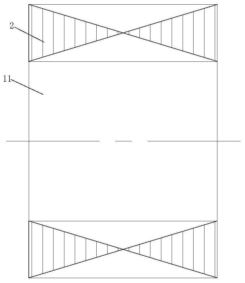
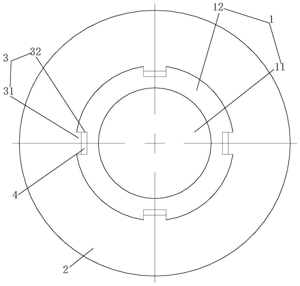
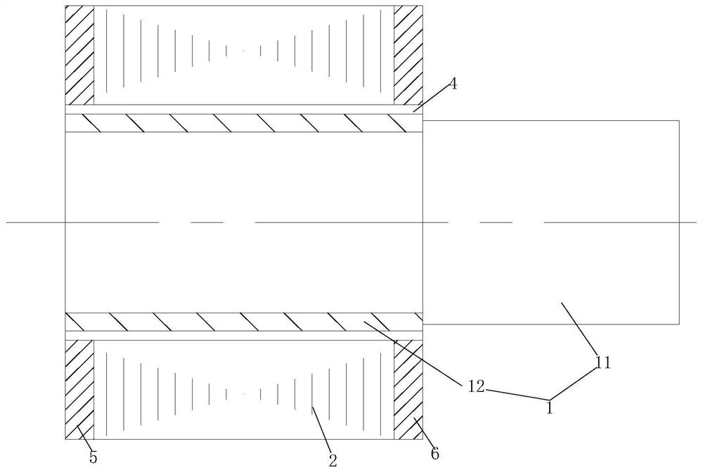
[0047] Such as Figure 1 to Figure 6, the circumferential limiting structure 3 includes a positioning protrusion 31 and a positioning groove 32 . Wherein, the positioning protrusion 31 is provided on the inner circle of the rotor lamination 2; the positioning groove 32 is provided on the outer side of the shaft assembly 1; At this time, the positioning protrusion 31 is matched and embedded in the positioning groove 32 . Positioning protrusions 31 are set on the inner circle of the rotor laminations 2, and cooperate with the positioning grooves 32 set on the shaft assembly 1 to play the role of circumferential limit, and then combined with the formed cooling channel 4, not only play a role The role of cooling the rotor structure of the magnetic suspension bearing improves the problem of rotor heating during the working process of the rotor structure of the magnetic suspension bearing, avoids the reduction of the working performance of the rotor structure of the magnetic suspen...

Embodiment 2

[0053] In this embodiment 2, the magnetic suspension bearing rotor structure of this embodiment is basically the same as that of the embodiment, the difference is that, as Figure 7 and Figure 8 , the rotating shaft assembly 1 includes a crankshaft 11; the positioning groove 32 is provided on the outer side of the crankshaft 11; The magnetic suspension bearing rotor structure is composed of a shaft assembly 1 , a rotor lamination 2 , a positioning protrusion 31 , a positioning groove 32 , a crankshaft 11 , a first baffle 5 and a second baffle 6 . Compared with the embodiment, the magnetic suspension bearing rotor structure of this embodiment has no collar 12 . When assembling, firstly, the rotor lamination 2 and the first baffle plate 5 and the second baffle plate 6 at both ends of the rotor lamination 2 are stacked together by tooling to form an integrated structure, the integrated structure is heated, and then sleeved on On the rotating shaft, at the same time, the corres...

Embodiment 3

[0055] In this third embodiment, the structure of the magnetic suspension bearing rotor in this embodiment is basically the same as that of the embodiment, the difference is that the positioning protrusion 31 is provided on the outer side of the shaft assembly 1; the positioning groove 32 is provided on the rotor stack On the inner circle of the sheet 2; when the rotor lamination 2 is sheathed on the outside of the shaft assembly 1, the positioning protrusion 31 is matched and embedded in the positioning groove 32. Specifically, such as Figure 9 and Figure 10 , the positioning groove 32 is provided on the inner circle of the rotor lamination 2; the positioning protrusion 31 is provided on the outer side of the collar 12; when the rotor lamination 2 is sleeved outside the collar 12 , the positioning protrusion 31 is matched and embedded in the positioning groove 32 . The positions of the positioning protrusions 31 and the positioning grooves 32 on the rotor laminations 2 an...


PUM


Abstract

The invention relates to a magnetic suspension bearing rotor structure. The magnetic suspension bearing rotor structure comprises a rotary shaft assembly, and the rotary shaft assembly is sleeved witha rotor pack in a matched mode; a circumferential limiting structure is arranged between the outer side of the rotary shaft assembly and the inner circle of the rotor pack and comprises a positioninggroove and a positioning protrusion capable of being embedded into the positioning groove in a mutually-matched mode; the two sides of the positioning protrusion are matched with the two sides of thepositioning groove; the lengths of the two ends of the positioning protrusion are smaller than the lengths of the two ends of the positioning groove; and after the positioning protrusion is embeddedinto the positioning groove, a cooling flow pass is formed between the end face of the positioning protrusion and the positioning groove. A cooling medium can pass through the cooling flow pass to achieve the cooling effect, the working property of the magnetic suspension bearing rotor structure is prevented from being lowered, the rotor pack and the rotary shaft assembly are prevented from rotating relatively, and the magnitude of interference of the rotor pack and the rotary shaft assembly can be decreased to improve safety. The invention further provides the motor with the magnetic suspension bearing rotor structure, and an air conditioner.

Description

technical field [0001] The invention relates to the technical field of motors, in particular to a magnetic suspension bearing rotor structure; and also provides a motor and an air conditioner with the magnetic suspension bearing rotor structure. Background technique [0002] The magnetic suspension bearing rotor is a part of the magnetic suspension bearing, and is mostly assembled on the main shaft. It cooperates with the magnetic suspension bearing stator, so that the rotor and the main shaft are suspended in the middle position. Since the working principle of the magnetic suspension bearing is that the magnetic suspension bearing stator coil generates magnetic flux after it is energized, from the bearing stator core, the bearing rotor, and then back to the bearing stator core to form a loop, so the magnetic suspension bearing rotor is usually used with good magnetic performance. On the other hand, in order to reduce iron loss, magnetic material laminations are usually used...

Claims


Application Information

Patent Timeline
Patent Type & Authority Patents(China)
IPC IPC(8): F16C32/04F16C37/00
CPCF16C32/044F16C37/005
Inventor 李欣张小波张芳龚高张超王建辉
Owner GREE ELECTRIC APPLIANCES INC
Learn More