
Wear-resistant pipeline compensator for electric power

A pipeline compensator, wear-resistant technology, applied in expansion compensation devices for pipelines, pipe components, pipes/pipe joints/fittings, etc., which can solve the damage of the corrugated joints of pipeline compensators and the low service life of protective pipes , pipeline compensator damage and other problems, to achieve the effect of improving the service life, ensuring the service life and improving the service life

Inactive Publication Date: 2020-04-03
TENGZHOU HUAZHENG SOFT JOINT CO LTD
View PDF6 Cites 2 Cited by
  • Summary
  • Abstract
  • Description
  • Claims
  • Application Information

AI Technical Summary

Problems solved by technology

[0004] In the electric power industry, it is necessary to use fuel to generate electricity. After the fuel is used, slag is formed. The discharge of slag also needs to use pipelines. In order to ensure the safe operation of pipelines, bellows compensators are often installed in pipelines to absorb or compensate pipeline Axial displacement, because the slag produced by the fuel is high temperature and solid particles, it is easy to damage the corrugated part of the pipeline compensator and cause rupture. The existing solution technology is to shield and protect the corrugated part by welding the protective tube on the inner wall of the pipeline compensator , to avoid being directly worn by the slag, but the protective tube is directly in contact with the slag, so the service life of the protective tube is low. At the same time, it is a welded structure with the pipeline compensator, so it only ensures that the service life of the pipeline compensator is partially improved, and cannot be effectively solved. This phenomenon, when the protective tube is worn out, will still cause damage to the pipeline compensator for replacement

Method used


Image

  • Wear-resistant pipeline compensator for electric power
  • Wear-resistant pipeline compensator for electric power
  • Wear-resistant pipeline compensator for electric power

Examples


Embodiment Construction

[0026] The present invention will be further described below in conjunction with the accompanying drawings and embodiments.

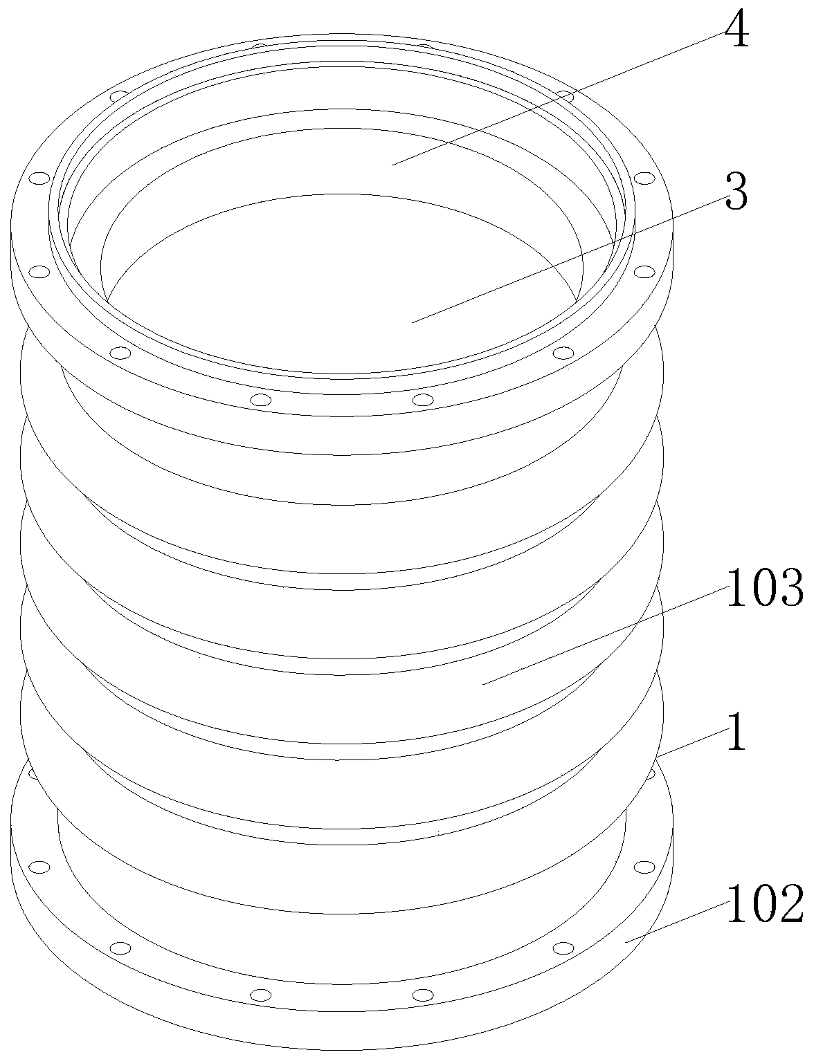
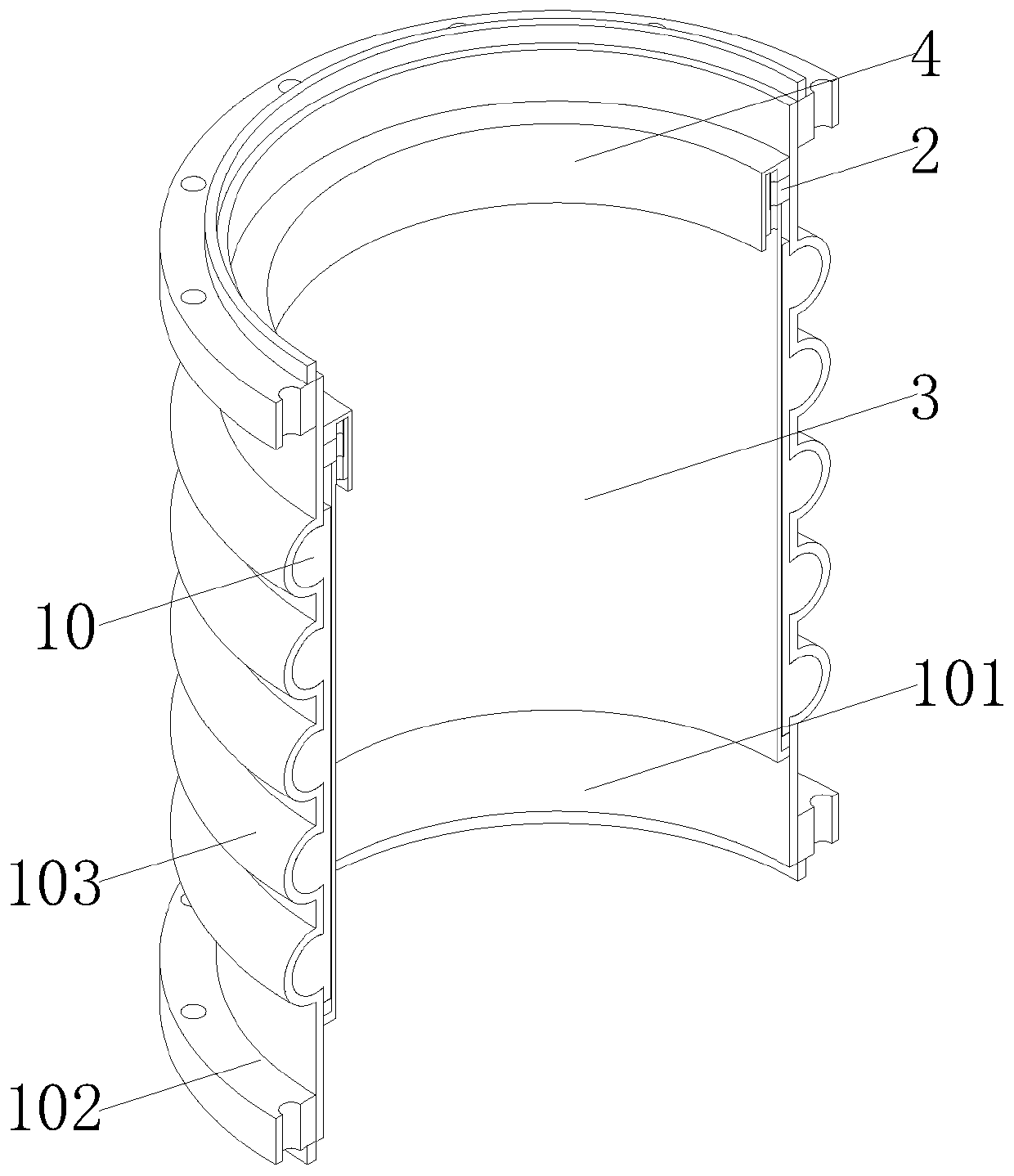
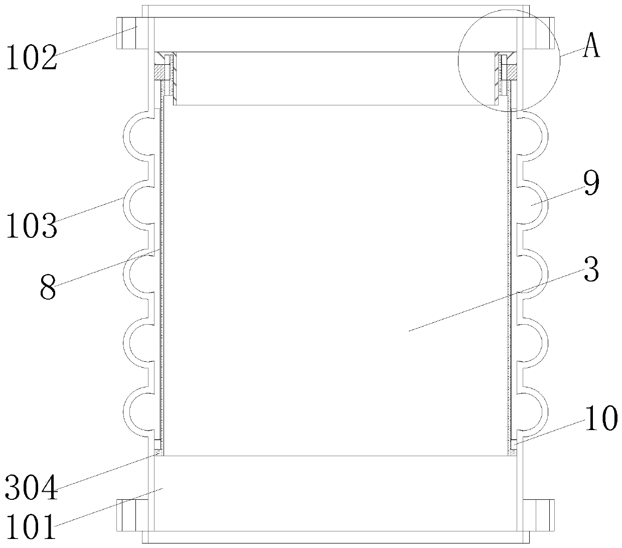
[0027] Please refer to figure 1 , figure 2 , image 3 and Figure 4 ,in, figure 1 It is a three-dimensional view of the structure of the present invention; figure 2 It is a three-dimensional sectional view of the structure of the present invention; image 3 It is a cross-sectional view of the structure of the present invention; Figure 4 for image 3 The enlarged schematic diagram of the structure in A. A wear-resistant pipeline compensator for electric power, including a compensator body 1, the compensator body 1 includes a compensation tube 101, a number of corrugated joints 103 are arranged in the middle of the compensation tube 101, and the inner wall of the compensation tube 101 is close to one of them The position of the opening is welded with a mounting ring 2, the top of the mounting ring 2 is provided with a protective cover 3, and th...


PUM


Abstract

The invention provides a wear-resistant pipeline compensator for electric power. The wear-resistant pipeline compensator for electric power comprises a compensator body, wherein the compensator body comprises a compensation pipe, a plurality of corrugated segments are arranged in the middle of the compensation pipe, a mounting ring is welded to the position, close to one opening, of the inner wallof the compensation pipe, a protective cover is arranged at the top of the mounting ring, and a wear-resistant pad is arranged at the top of the mounting ring. The mounting ring is directly welded tothe inner wall of the compensation pipe to provide positions for mounting the protective cover and the wear pad. The mounting ring, the protective cover and the wear-resistant pad are directly detachably fixed. After the protective cover and the wear-resistant pad are damaged, replacement can be carried out, and the pipeline compensator can be prevented from being directly replaced. The wear-resistant pad can achieve a protective effect on the mounting ring. Slag enters the compensation pipe from one end provided with the wear-resistant pad and makes direct contact with the wear-resistant pad, so that the mounting ring can be protected, and long service life of the mounting ring is ensured.

Description

technical field [0001] The invention relates to the field of pipeline compensators, in particular to a wear-resistant pipeline compensator for electric power. Background technique [0002] Pipeline compensators, also known as expanders or expansion joints, expansion joints, are mainly used to compensate for thermal expansion and contraction of pipelines caused by temperature changes. If the pipe is not completely free to expand or contract when the temperature changes, thermal stresses will develop in the pipe. This stress must be considered in the pipeline design, otherwise it may cause the rupture of the pipeline and affect the normal production. As an important part of pipeline engineering, compensators play an important role in ensuring the long-term normal operation of pipelines. [0003] There are many types of pipeline compensators, which are divided into axial type, transverse type, angular type and pressure balance type according to the compensation type; the axia...

Claims


Application Information

Patent Timeline
Patent Type & Authority Applications(China)
IPC IPC(8): F16L51/02
CPCF16L51/025
Inventor 赵兴赵景尧赵屹嘉
Owner TENGZHOU HUAZHENG SOFT JOINT CO LTD
Learn More