Knurling press-in special-shaped terminal hole connector

A special-shaped terminal and connecting terminal technology, applied in the direction of connecting contact materials, contact parts, etc., can solve the problems of difficult assembly, terminal temperature rise, weak electrical performance, etc., to ensure the stability of electrical performance, improve assembly efficiency, and save money. cost effect

Pending Publication Date: 2020-04-03
苏州鲁益电子科技有限公司
View PDF0 Cites 0 Cited by
  • Summary
  • Abstract
  • Description
  • Claims
  • Application Information

AI Technical Summary

Problems solved by technology

This type of connector is an industrial connector used in industries such as photovoltaics and lamps. Its main advantage is that it is easy to plug and unplug. However, the process of assembling wires for connector products is complicated, and parts are easily missed, resulting in various defects. High professional quality requirements, and high requirements for waterproof and dustproof
At present, the mainstream terminal installation method in the market adopts forced interference or shrapnel structure assembly, but forced interference press-in requires too much pressure and makes assembly difficult; press-in shrapnel structure will cause weak electrical performance and high terminal temperature rise

Method used


Image

  • Knurling press-in special-shaped terminal hole connector
  • Knurling press-in special-shaped terminal hole connector
  • Knurling press-in special-shaped terminal hole connector

Examples


Embodiment 1

[0023] The present invention will be further described below in conjunction with accompanying drawing and embodiment:

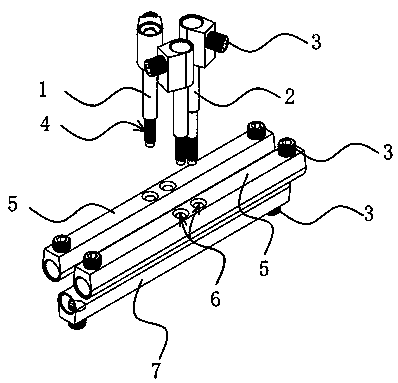
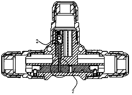
[0024] figure 1 , 3, 4 The integrated terminal includes a special-shaped terminal 5, upper terminals 1, 2, countersunk head screws 3 and rubber cores, the special-shaped terminal has a number of connection holes 6 that match the upper terminal, and the upper There is a knurled structure 4 at the front end of the terminal.

[0025] figure 1 As shown, the special-shaped terminal 5 is in a U shape as a whole, with wire insertion holes and threaded holes at both ends, and a terminal connection hole 6 in the middle, and the terminal connection hole 6 is symmetrical about the center.

[0026] figure 1 As shown, the tails of the upper terminals 1 and 2 are U-shaped, and the U-shape includes a wire insertion hole and a threaded hole. The middle part of the upper terminal is cylindrical and connected to the knurled structure. The knurl structure is provided with a...

Embodiment 2

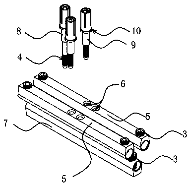
[0029] figure 2 , as shown in 5 and 6, the plug-in terminal structure, in this embodiment, its structure is basically similar to that of Embodiment 1, the difference is that: the upper terminal 2 is changed to a female terminal and a male terminal, and the matching male and female terminals are installed The rubber cores are the female end and the male end of the connector respectively. The female terminal and the male terminal are provided with a terminal force-receiving round table 10, which is used to limit the over-insertion of the terminal and prevent the deformation of the male / female terminal.


PUM


Abstract

The invention relates to a knurling press-in special-shaped terminal hole connector, especially to a connector structure of electronic components. The electric connector comprises an integrated terminal structure and a plug-in terminal structure. The integrated terminal comprises a special-shaped terminal, an upper terminal, a countersunk head screw and a rubber core, the special-shaped terminal is provided with a plurality of connecting holes matched with the upper terminal, the upper terminal is provided with an end knurling structure, and the plug-in terminal is characterized in that the upper terminal in the integrated terminal structure can be changed into a female terminal or a male terminal and can be arranged in a matched male-female rubber core. The novel terminal structure is designed, knurls are pressed into the special-shaped terminal holes, forced interference pressure is not needed, assembling is convenient, an elastic piece anti-retreating structure is not needed, the cost is saved, the assembling efficiency is improved, and the electrical performance stability of the terminal is guaranteed.

Description

technical field [0001] The invention relates to a connector for electronic components, in particular to a knurling press-fit connection terminal in a special-shaped terminal hole. Background technique [0002] Connectors are an important part of electronic equipment. They serve as a bridge for communication between blocked or isolated circuits in the circuit, so that current can flow and the circuit can achieve predetermined functions. This type of connector is an industrial connector used in industries such as photovoltaics and lamps. Its main advantage is that it is easy to plug and unplug. However, the process of assembling wires for connector products is complicated, and parts are easily missed, resulting in various defects. High professional quality requirements, and high requirements for waterproof and dustproof. At present, the mainstream terminal installation method in the market adopts forced interference or shrapnel structure assembly, but forced interference pres...

Claims


Application Information

Patent Timeline
Patent Type & Authority Applications(China)
IPC IPC(8): H01R13/02H01R4/58
CPCH01R4/58H01R13/02
Inventor 崔红伟
Owner 苏州鲁益电子科技有限公司
Why Eureka
Try Eureka