
Photovoltaic support angle adjusting structure

A photovoltaic bracket and angle adjustment technology, which is applied to the support structure of photovoltaic modules, photovoltaic modules, photovoltaic power generation, etc., can solve problems such as unstable structures, low safety performance, and large shaking gaps, and achieve time-saving and labor-saving adjustments during the adjustment process. Low maintenance cost, fast and convenient installation

Inactive Publication Date: 2020-04-03
SHANDONG ZHAORI PV TECH CO LTD
View PDF0 Cites 0 Cited by
  • Summary
  • Abstract
  • Description
  • Claims
  • Application Information

AI Technical Summary

Problems solved by technology

[0003] The purpose of the present invention is to provide a photovoltaic support angle adjustment structure, which is used to solve the existing angle adjustment schemes with complex structure, cumbersome transportation and installation, many hinge points, large shaking gap, unstable structure, and easy resonance. There are many problems such as no self-locking function, low safety performance, high equipment cost and high maintenance cost

Method used


Image

  • Photovoltaic support angle adjusting structure
  • Photovoltaic support angle adjusting structure
  • Photovoltaic support angle adjusting structure

Examples


Embodiment 1

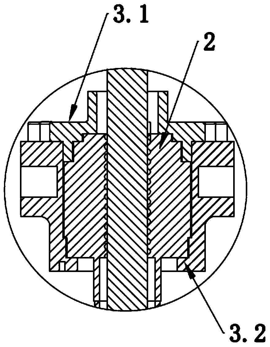
[0031] Such as Figure 1-3 as well as Figure 8 As shown, a structure for adjusting the angle of a photovoltaic bracket includes a screw 1 , a screw nut 2 , a housing 3 and a handle 4 .

[0032] The housing 3 is hingedly mounted on the column 6 of the photovoltaic support. The housing 3 is a box, including an upper housing 3.1 and a lower housing 3.2. The two are fixedly connected to form the housing 3. The fixing method can be threaded connection , Bonding, welding, bolting, pinning and other connection methods. The upper shell 3.1 and the lower shell 3.2 can be obtained by casting, forging, stamping, welding, etc., and the material can be nylon, metal and other materials. Both the upper housing 3.1 and the lower housing 3.2 are provided with holes corresponding to the inner cavity of the screw nut 2 , and the size of the holes is smaller than the diameter of the screw nut 2 . The screw nut 2 is rotatably installed in the housing 3 , and its inner cavity is penetrated and ...

Embodiment 2

[0036] In order to further enhance the stability, environmental adaptability and service life of the photovoltaic support angle adjustment structure, the structure is further improved as follows.

[0037] A bearing 11 is respectively inlaid on the upper casing 3.1 and the lower casing 3.2, and the screw nut 2 is hinged with the bearing 11 on the upper casing 3.1 and the lower casing 3.2, so as to reduce the contact between the upper and lower ends of the screw nut 2 and the bearing 11 respectively. The frictional force of the upper housing 3.1 and the lower housing 3.2 makes the adjustment easier and ensures the rotation accuracy.

[0038] On the upper shell 3.1, a screw protective inner shell 7 is fixedly installed, and the fixing methods are welding, threaded connection, bonding, bolting, pin connection, etc., and its material is nylon, metal and other materials; the screw rod 1 is set on the wire In the rod protection inner shell 7. A screw mandrel protective shell 8 is sh...


PUM


Abstract

The invention aims to provide a photovoltaic support angle adjusting structure which is used for solving the problems that an existing angle adjusting scheme is complex in structure, tedious in transportation and installation, multiple in hinge points, large in shaking gap, unstable in structure, prone to generating resonance, free of a self-locking function in the adjusting process, low in safetyperformance, high in equipment cost, high in later maintenance cost and the like. The photovoltaic support angle adjusting structure comprises a lead screw, a lead screw nut, a shell and a rocking handle. The shell is hinged to the stand column of a photovoltaic support, the lead screw nut is located in the shell, and the rocking handle is connected with the lead screw nut. The lead screw is matched with the lead screw nut in a threaded connection mode, one end of the lead screw is rotatably connected with a rotating component on the stand column, and the other end of the lead screw is sleeved with the rocking handle.

Description

technical field [0001] The invention relates to the technical field of photovoltaic support angle adjustment devices, in particular to a photovoltaic support angle adjustment structure. Background technique [0002] Among the angle adjustment schemes of photovoltaic supports in the prior art, some adopt the jack adjustment scheme, which has many hinge points, large shaking gap, unstable structure, complicated installation, high maintenance cost in the later stage, poor protection performance, and exposed screw rods It is easy to be affected by the external environment, and under special circumstances, the adjustment requires high-altitude operations; some use semi-circular adjustment, pole adjustment and other schemes, which have the disadvantages of no self-locking function during adjustment, and great potential safety hazards. Contents of the invention [0003] The purpose of the present invention is to provide a photovoltaic support angle adjustment structure, which is ...

Claims


Application Information

Patent Timeline
Patent Type & Authority Applications(China)
IPC IPC(8): H02S20/30F24S30/422
CPCF24S25/12F24S30/422H02S20/30Y02E10/47Y02E10/50
Inventor 刘建中王稳稳孙涛
Owner SHANDONG ZHAORI PV TECH CO LTD
Learn More