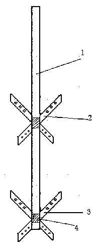
Stirring paddle for reaction kettle

A stirring paddle and reaction kettle technology, applied in chemical/physical/physical-chemical processes, chemical instruments and methods, chemical/physical processes, etc., can solve the impact of reflected progress, product production efficiency, inability to meet market demand, motor power Large and other problems, to achieve the effect of reducing power requirements, reducing weight, and saving energy

Inactive Publication Date: 2020-04-07
泰兴市宏伟机电环保科技有限公司
View PDF0 Cites 0 Cited by
  • Summary
  • Abstract
  • Description
  • Claims
  • Application Information

AI Technical Summary

Problems solved by technology

The stirring paddle is an important part of the reactor. Currently, the commonly used stirring paddles include single-row blades and double-row blades. In the process of

Method used


Image

  • Stirring paddle for reaction kettle

Examples


Example Embodiment

[0010] In order to further understand the stirring paddle with rotating blades, the description is as follows in conjunction with the figure:

[0011] It includes: a stirring shaft 1 and a blade group 2, the blade group 2 is composed of two mutually intersecting blades, the included angle between the two blades is 30-60 degrees, and the blade body is provided with a through hole 3, The diameter of the through hole 3 is 10~20mm, and the distance between the through holes 3 is the same. It is characterized in that: a bearing 4 is arranged between the blade group 2 and the stirring shaft 1, and a sealing sleeve is arranged outside the bearing 4; the blade group 2 is controlled by Motor control; the blade group 2 rotates with the stirring shaft 1 as the central axis.

[0012] The blade group 2 is a double-row structure, and the distance between the two rows of blade groups 2 is 30-50 cm.

[0013] The blades are made of high-precision ceramic materials.


PUM

PropertyMeasurementUnit
Angleaaaaaaaaaa
Diameteraaaaaaaaaa

Abstract

The invention relates to a stirring paddle, and particularly relates to a stirring paddle for a reaction kettle, which belongs to the field of chemical equipment. The stirring paddle blade adopts a structure with a through hole, the materials can be thoroughly stirred, the stirring weight is reduced, the requirements on the power of the reaction kettle are reduced, and energy is saved; and when arotating shaft does not rotate, the blade is driven by a control motor to rotate to achieve the stirring function. When the stirring shaft rotates, the blade rotates along with the stirring shaft, therelative rotating speed of the blade is increased, and stirring efficiency is improved.

Description

technical field [0001] The invention relates to a stirring paddle, in particular to a stirring paddle for a reaction kettle, which belongs to the field of chemical equipment. Background technique [0002] With the development of science and technology and social progress, the chemical industry has developed rapidly, and people's quality requirements for chemical products are also constantly improving. The primary factor affecting the quality of chemical products is the reaction equipment, and the reactor is the most important in the reaction equipment. equipment. The stirring paddle is an important part of the reactor. Currently, the commonly used stirring paddles include single-row blades and double-row blades. The energy consumption is large during the reflection process, which affects the progress of the reflection and the production efficiency of the product, and it cannot meet the demand of the market. Contents of the invention [0003] In view of the defects existi...

Claims


Application Information

Patent Timeline
IPC IPC(8): B01J19/00
CPCB01J19/0066
Inventor 戴金龙
Owner 泰兴市宏伟机电环保科技有限公司
Why Eureka
Try Eureka