Roller of aluminum tube rolling mill

A rolling mill and roll technology, applied in the field of aluminum tube processing equipment, can solve the problems of short life and breakage of the roll, and achieve the effects of improving production efficiency, good bearing capacity and ensuring service life

Inactive Publication Date: 2020-04-07
湖北莲花电力母线制造有限公司
View PDF0 Cites 0 Cited by
  • Summary
  • Abstract
  • Description
  • Claims
  • Application Information

AI Technical Summary

Problems solved by technology

[0005] In order to solve the problem that the existing roll often breaks at the joint between the roll shaft and the roll body, resulting in short life of the roll, the present invention provides a new type of aluminum tube mill roll that can effectively solve the problem of fracture at the joint between the roll shaft and the roll body

Method used


Image

  • Roller of aluminum tube rolling mill
  • Roller of aluminum tube rolling mill

Examples


Embodiment Construction

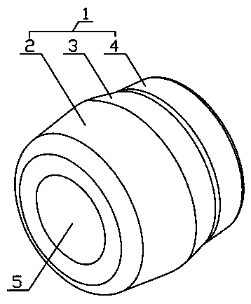
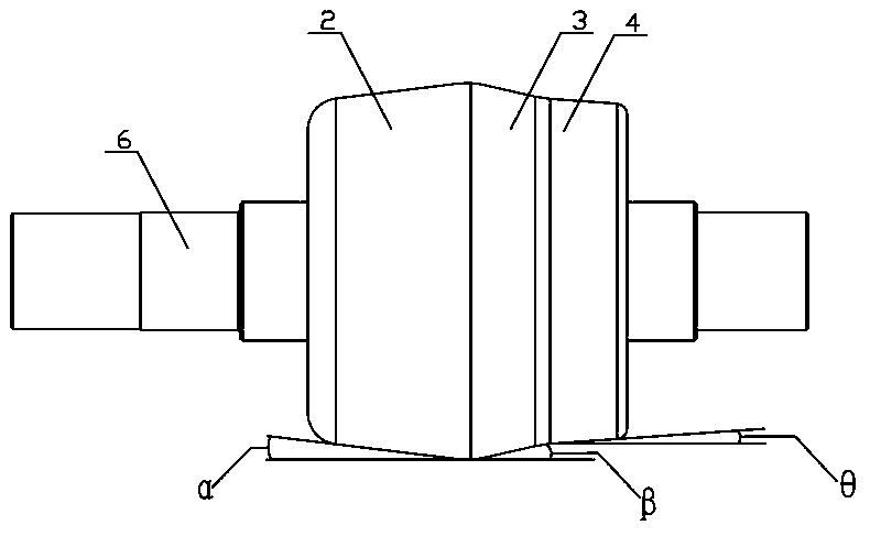
[0014] In this embodiment, a roll of an aluminum tube rolling mill has a roll body 1, and the roll body 1 is divided into a feed side and a discharge side along the roll peak, one left and one right, and the feed side is a diameter gradually along the feed direction. Increased circular cone A2, the feed angle α formed by the conical surface of the circular cone A2 in the horizontal direction is 6°, and the discharge side is successively composed of a circular shape whose diameter gradually decreases along the discharge direction. The cone B3 and the circular cone C4 are formed, and the discharge angle β and the discharge angle θ formed by the conical surfaces of the circular cone B3 and the circular cone C4 in the horizontal direction are 13° and 4° respectively.

[0015] In this embodiment, the roller body 1 is provided with a central through hole 5, and the roller shaft 6 is interference-fitted in the central through hole 5, and the center line of the roller body 1 and the ro...


PUM


Abstract

The invention relates to the field of aluminum tube machining equipment, in particular to a roller of an aluminum tube rolling mill. The roller comprises a roller body. The roller body is provided with a feeding side and a discharging side on the left side and the right side of a roller peak, wherein the feeding side forms a feeding angle alpha of 6 degrees in the horizontal direction, and the discharging side forms a discharging angle beta of 13 degrees and a discharging angle theta of 4 degrees in the horizontal direction. A central through hole is formed in the roller body and is internallyin interference fit with a roller shaft. The roller body is prepared from 45# steel through forging. The roller shaft is prepared from 40Cr steel through forging. Through the combination mode of the45# steel (roller body) and the 40Cr steel (roller shaft), the phenomenon that cracks easily appear in the joint of the roller body and the roller shaft is solved, and the service life of the roller shaft is effectively ensured.

Description

technical field [0001] The invention relates to the field of aluminum tube processing equipment, in particular to an aluminum tube rolling mill roll. Background technique [0002] The roll is the main part of the aluminum tube rolling mill to roll the tube blank (waste tube). In the existing rolls, the roll body and the roll shaft are mostly integrated structures. The following problems exist in the rolling process: [0003] 1. The current roll body and the roll body are all forged from 45# steel in one piece. This steel has good wear resistance and impact resistance after quenching and tempering, but its ability to withstand concentrated stress is poor. In the waste management process, there is a large concentrated stress at the joint between the roll shaft and the roll body. Therefore, the existing rolls often break at the joint between the roll shaft and the roll body. After the breakage occurs, the entire roll will be discarded directly. , resulting in a large waste; ...

Claims


Application Information

Patent Timeline
Patent Type & Authority Applications(China)
IPC IPC(8): B21B27/02
CPCB21B27/024
Inventor 周泱郑小刚
Owner 湖北莲花电力母线制造有限公司
Why Eureka
Try Eureka