Large-span steel box hybrid beam short combination section structure of high-speed rail

A steel-concrete combination and hybrid beam technology, which is applied in bridges, bridge parts, bridge construction, etc., can solve the problems of long joint section, inconvenient construction, local self-heavyness, etc., to achieve enhanced stability, simple construction and installation, and improved force bearing and force transfer performance

Pending Publication Date: 2020-04-07
SOUTHWEST JIAOTONG UNIV +2
View PDF0 Cites 3 Cited by
  • Summary
  • Abstract
  • Description
  • Claims
  • Application Information

AI Technical Summary

Problems solved by technology

The steel-concrete joint transmits huge internal force of the main girder between the two materials, which has the characteristics of complex structure and complex force transmission; most of the existing mixed-girder cable-stayed bridges are highway bridges. High, resulting in less application in railway bridges
[0003] Among the long-span steel-concrete composite box-girder cable-stayed bridges for railways, the Ningbo Railway Hub Yongjiang Super Bridge and the Shenmao Railway

Method used


Image

  • Large-span steel box hybrid beam short combination section structure of high-speed rail
  • Large-span steel box hybrid beam short combination section structure of high-speed rail
  • Large-span steel box hybrid beam short combination section structure of high-speed rail

Examples


Example Embodiment

[0033] Example 1

[0034] refer to Figure 1-10 , the present invention provides a technical solution:

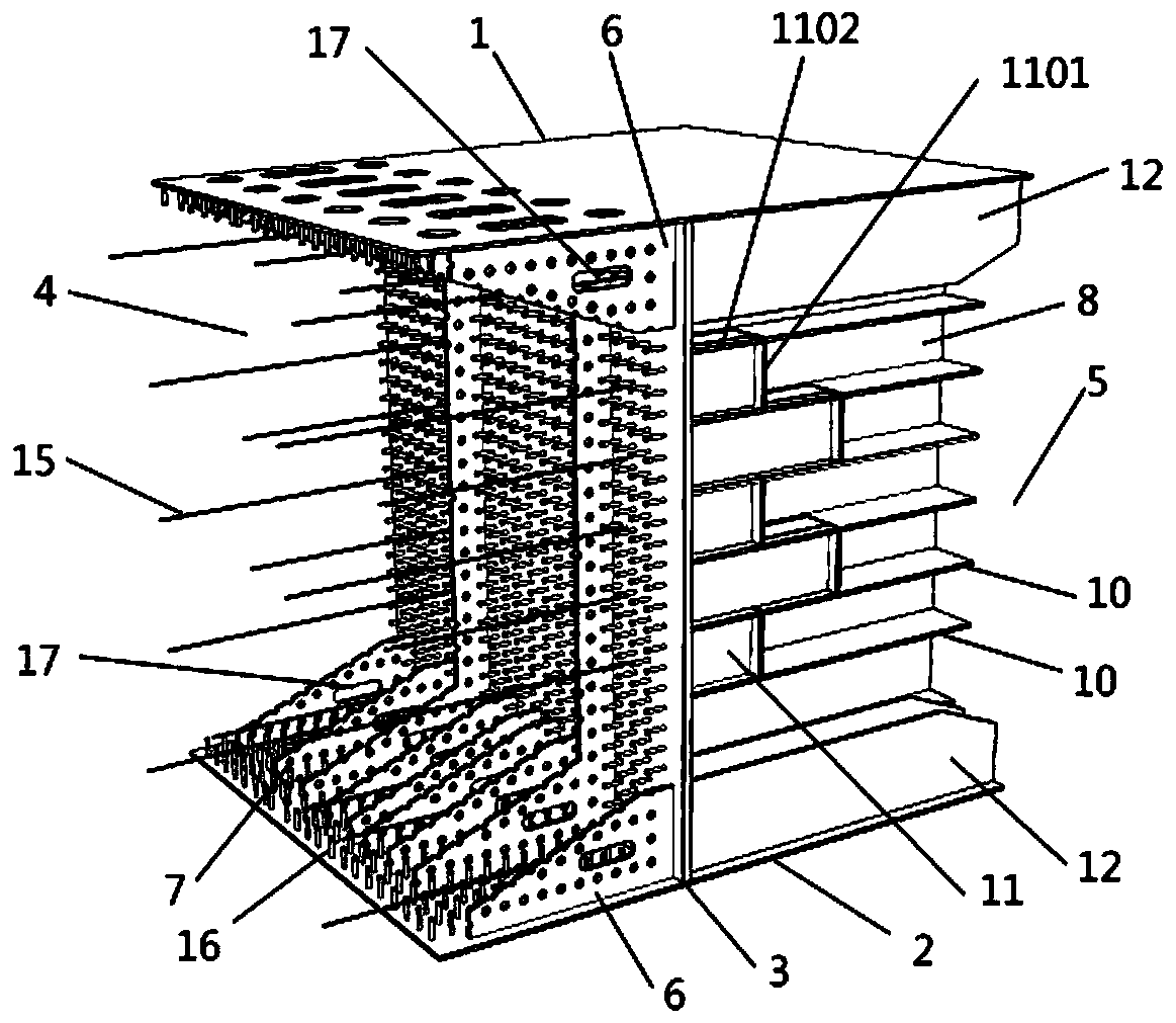
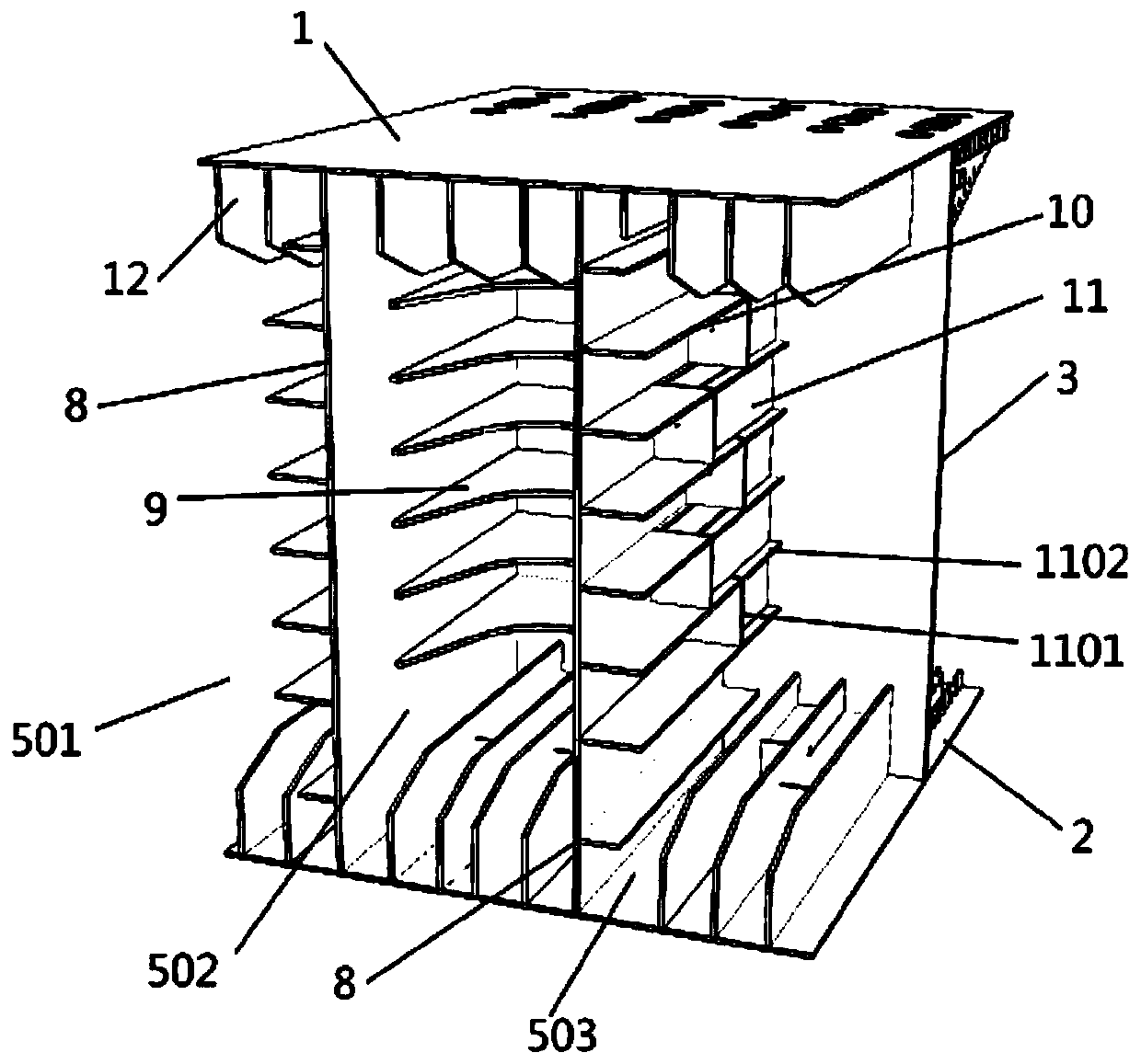
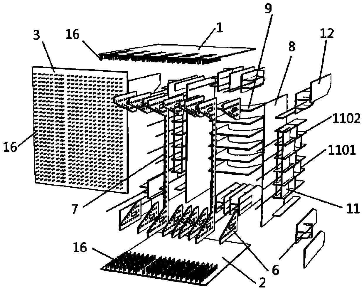
[0035] Please refer to Figure 1-3 and Image 6 , a high-speed rail long-span steel box mixed beam short joint section structure, including a steel top plate 1, a steel bottom plate 2 and a pressure bearing plate 3, and the pressure bearing plate 3 is sandwiched between the steel top plate 1 and the steel bottom plate 2 And in the longitudinal bridge direction, the short joint section of steel box composite girder is divided into steel-concrete joint section 4 and steel beam transition section 5;

[0036] Both ends of the steel top plate 1 and the steel bottom plate 2 in the steel-concrete joint section 4 are equipped with PBL perforated steel plates 6 parallel to the longitudinal bridge direction, and between the PBL perforated steel plates 6 at both ends of the steel top plate 1 and the steel bottom plate 2 Multiple C-shaped perforated steel plates 7 are installed bet...


PUM

PropertyMeasurementUnit
Diameteraaaaaaaaaa
Heightaaaaaaaaaa

Abstract

The invention discloses a large-span steel box hybrid beam short combination section structure of a high-speed rail which comprises a steel top plate, a steel bottom plate and a bearing plate, and thebearing plate is clamped between the steel top plate and the steel bottom plate and divides a steel box hybrid beam short combination section into a steel-concrete combination section and a steel beam transition section in the longitudinal bridge direction. Two steel webs of the transition section divide the steel beam transition section into a box girder outer chamber, a box girder compartment and a box girder inner chamber in the transverse bridge direction, PBL steel bars transversely penetrate through PBL perforated steel plates and C-shaped perforated steel plates on a steel top plate and a steel bottom plate of the steel-concrete combined section, and a concrete partition wall is poured in the steel-concrete combined section; the transition section steel top plate, the bottom and the web plate are provided with prestressed tendon anchor chambers, longitudinal prestressed reinforcements are anchored in the prestressed tendon anchor chambers, and the prestressed reinforcements penetrate through the bearing plate and the steel-concrete combined section and are anchored on the concrete beam section behind the combined section so as to reinforce connection between the bearing plate and the concrete partition wall. A short combination section structure has the advantages of being simple in structure, short in combination part, high in bearing capacity, convenient to constructand small in operation and maintenance workload.

Description

technical field [0001] The invention relates to the field of design and construction of bridge engineering, in particular to a short joint section structure of a large-span steel box composite beam for high-speed railways. Background technique [0002] The side spans of steel-concrete composite box girder cable-stayed bridges use concrete girders, which can balance the self-weight of the mid-span and long-span steel girders, and the side-span concrete girders can also increase the overall rigidity of the main girder. In addition, the side-span concrete girders reduce the steel consumption of the whole bridge, which improves the economy and subsequent maintenance costs. The steel-concrete joint transmits huge internal force of the main girder between the two materials, which has the characteristics of complex structure and complex force transmission; most of the existing mixed-girder cable-stayed bridges are highway bridges. High, resulting in less application in railway bri...

Claims


Application Information

Patent Timeline
IPC IPC(8): E01D19/00E01D2/04E01D21/00
CPCE01D2/04E01D19/00E01D21/00
Inventor 施洲李思阳宁伯伟石建华李世文张巨生方绪镯李江刚
Owner SOUTHWEST JIAOTONG UNIV
Why Eureka
Try Eureka