
Oil separator used for compressor, compressor and refrigeration system

An oil separator and refrigeration system technology, applied in the direction of compressors, refrigerators, refrigeration components, etc., can solve the problems of large exhaust resistance of compressors, decreased heat exchange efficiency of condensers and evaporators, and unstable oil level, etc. Achieve the effect of reducing oil discharge rate, improving performance and improving oil and gas separation efficiency

Pending Publication Date: 2020-04-07
GUANGDONG WELLING AUTO PARTS CO LTD
View PDF0 Cites 2 Cited by
  • Summary
  • Abstract
  • Description
  • Claims
  • Application Information

AI Technical Summary

Problems solved by technology

However, due to the small space of the car, the weight and volume requirements of the compressor are relatively strict, and the compressor is required to be small in size and light in weight. It will cause the oil seal volume of the compressor to be too small and the oil-gas separation space to be too small, so that the installation of the oil-gas separation device cannot be realized or the installed oil-gas separation device cannot effectively realize the oil-gas separation, resulting in a large oil discharge volume of the compressor and an unstable oil surface. Moreover, the exhaust resistance of the compressor is large, and it will also cause a decrease in the heat exchange efficiency of the condenser and evaporator, which will affect the heat exchange capacity of the automotive air conditioning system and customer experience.

Method used


Image

  • Oil separator used for compressor, compressor and refrigeration system
  • Oil separator used for compressor, compressor and refrigeration system
  • Oil separator used for compressor, compressor and refrigeration system

Examples


Embodiment Construction

[0037] Specific embodiments of the present invention will be described in detail below in conjunction with the accompanying drawings. It should be understood that the specific embodiments described here are only used to illustrate and explain the present invention, and are not intended to limit the present invention.

[0038] In the present invention, unless stated to the contrary, the used orientation words such as "upper, lower, top, and bottom" usually refer to the upper, lower, top, and bottom under the state of installation and use. "Inner and outer" refer to inner and outer relative to the outline of each component itself.

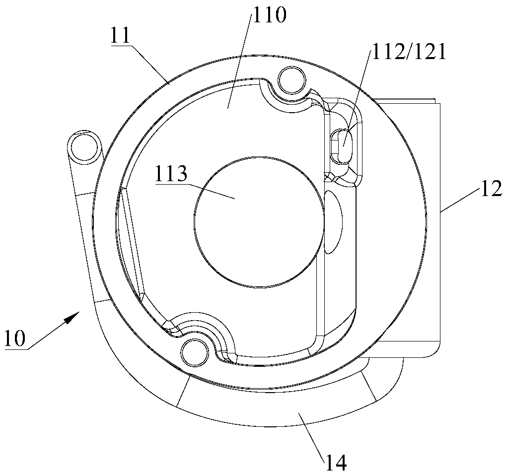
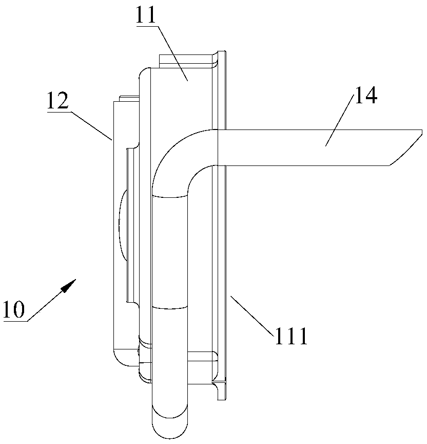
[0039] The first aspect of the present invention provides an oil separator for a compressor, the oil separator 10 is arranged in the compressor, the oil separator 10 includes an oil separation chamber 120 and a Oil outlet 122 and gas outlet 123, the oil outlet 122 is located at the bottom of the oil separation chamber 120, the gas outlet 123 is loca...


PUM


Abstract

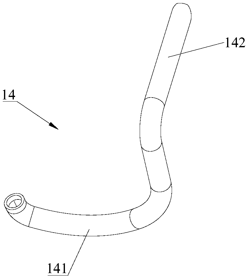
The invention relates to the technical field of refrigeration, and discloses an oil separator used for a compressor, the compressor and a refrigeration system. The oil separator (10) is arranged in the compressor and comprises an oil separation chamber (120), an oil liquid outlet (122) and a gas outlet (123), wherein the oil liquid outlet (122) and the gas outlet (123) communicate with the oil separation chamber (120); the oil liquid outlet (122) is positioned on the bottom of the oil separation chamber (120); the gas outlet (123) is positioned on the top of the oil separation chamber (120); the oil separator (10) comprises an oil returning pipe (14) connected to the oil liquid outlet (122); and the outlet pressure of the oil returning pipe (14) is equal to the pressure of the gas outlet (123). By use of the oil separator, oil and gas separation efficiency can be improved, an oil discharging rate is lowered, and the performance of the compressor is improved.

Description

technical field [0001] The invention relates to the technical field of refrigeration, in particular to an oil separator for a compressor, a compressor containing the oil separator and a refrigeration system containing the compressor. Background technique [0002] Compressors are commonly used in refrigeration systems, such as car air conditioners or home air conditioning systems. During the operation of the compressor, the friction and heat generation of the compression mechanism are serious, and it is necessary to use refrigerated lubricating oil to lubricate and cool down the compression mechanism to improve the reliability of the compressor operation. However, since the lubricating oil and the refrigerant have certain mutual solubility, and the refrigerant discharged into the compressor chamber by the compression mechanism is in a state of high temperature and high pressure, when the refrigerant is discharged out of the compressor from the compressor chamber, part of the ...

Claims


Application Information

Patent Timeline
IPC IPC(8): F25B43/02F25B31/00
CPCF25B31/004F25B43/02
Inventor 黎法运杨开成
Owner GUANGDONG WELLING AUTO PARTS CO LTD
Learn More