
Imaging method

An imaging method and azimuth angle technology, applied in the field of imaging, can solve the problems of not adapting to the three-dimensional imaging method of vortex electromagnetic waves, and achieve the effect of high-resolution imaging azimuth

Active Publication Date: 2020-04-07
SHANGHAI RADIO EQUIP RES INST
View PDF7 Cites 13 Cited by
  • Summary
  • Abstract
  • Description
  • Claims
  • Application Information

AI Technical Summary

Problems solved by technology

[0007] The purpose of the present invention is to provide an imaging method to solve the problem in the prior art that there is no vortex electromagnetic wave three-dimensional imaging method suitable for different detection distances in the field of radar imaging applications

Method used


Image

  • Imaging method
  • Imaging method
  • Imaging method

Examples


Embodiment Construction

[0031]As mentioned in the background, the current research on vortex electromagnetic waves mainly involves the generation of vortex electromagnetic waves, the design of orbital angular momentum antennas, and the multiplexing of vortex electromagnetic wave modes. Electromagnetic waves in the microwave band, where radar and communication are mainly concentrated, also have the property of vortex, and the application of vortex electromagnetic waves is mainly concentrated in the field of communication, and its research in the field of radar is still rare. For example, the publication number is CN106199600B, and the Chinese patent titled: Azimuth Multi-Channel Synthetic Aperture Radar Imaging Method Based on Doppler Estimation proposes an azimuth multi-channel Synthetic Aperture Radar imaging method based on Doppler estimation, which belongs to the traditional basis The radar imaging method based on the range-Doppler principle has limited radar detection capability. In the graduatio...


PUM


Abstract

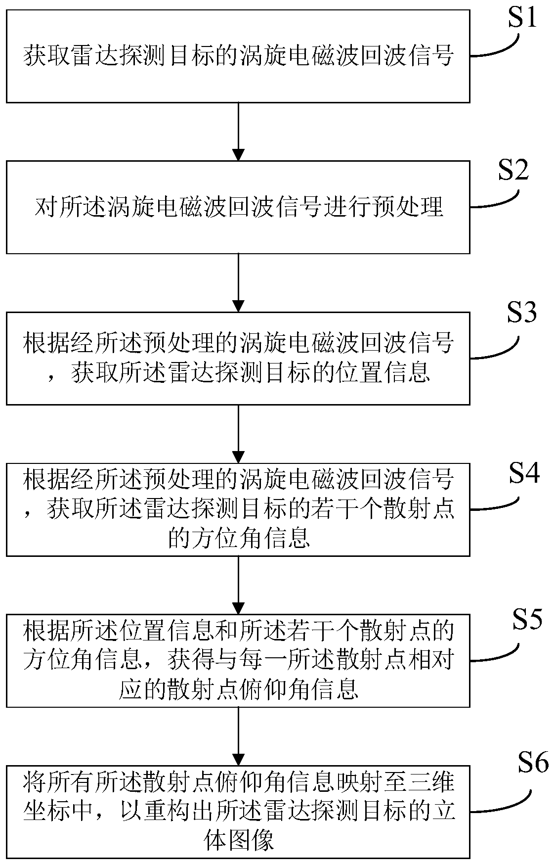
The invention discloses an imaging method. The imaging method comprises the following steps: S1, acquiring a vortex electromagnetic wave echo signal of a radar detection target; S2, preprocessing thevortex electromagnetic wave echo signal; S3, obtaining the position information of the radar detection target according to the preprocessed vortex electromagnetic wave echo signal; S4, obtaining azimuth angle information of a plurality of scattering points of the radar detection target according to the preprocessed vortex electromagnetic wave echo signals; S5, obtaining scattering point pitch angle information corresponding to each scattering point according to the position information and the azimuth angle information of the plurality of scattering points; and S6, mapping the pitch angle information of all the scattering points into a three-dimensional coordinate to reconstruct the three-dimensional image of the radar detection target. The invention provides a vortex electromagnetic wavethree-dimensional imaging method suitable for different distance detection.

Description

technical field [0001] The invention relates to the field of imaging technology, in particular to a radar imaging method. Background technique [0002] Radar imaging technology has the advantages of all-day and all-weather, and is not affected by natural conditions. The role of high-resolution imaging radar in military fields such as battlefield reconnaissance, air defense and anti-missile, and precision strikes has gradually become prominent. It has become the future development of many countries. Competing for the commanding heights. [0003] After decades of development, radar high-resolution imaging theory and technology have made great progress, and some results have also been applied in radar imaging systems. Overall, most methods are usually based on the range-Doppler principle. The resolution is obtained by transmitting a broadband signal, and the relative motion of the radar and the target forms a large virtual synthetic aperture. The acquisition of azimuth resolu...

Claims


Application Information

Patent Timeline
Patent Type & Authority Applications(China)
IPC IPC(8): G01S13/89G01S7/41
CPCG01S13/89G01S7/418Y02A90/10
Inventor 刘亚奇高亮陈斌张凤萍王海涛
Owner SHANGHAI RADIO EQUIP RES INST
Learn More