Magnesium oxide stirring device

A stirring device and magnesium oxide technology, which are applied in mixers with rotary stirring devices, mixer accessories, transportation and packaging, etc., can solve the problems of time-consuming and laborious, reduced work efficiency, and affecting the fluidity of magnesium oxide.

Inactive Publication Date: 2020-04-10
芜湖市皖镁实业有限公司
View PDF9 Cites 2 Cited by
  • Summary
  • Abstract
  • Description
  • Claims
  • Application Information

AI Technical Summary

Problems solved by technology

[0002] The production of magnesium sulfate is usually realized by the reaction between magnesium oxide and dilute sulfuric acid. Before the reaction between magnesium oxide and dilute sulfuric acid, it is necessary to add water and stir the magnesium oxide before entering the reaction furnace for reaction. The traditional stirring is done by manually adding water, which is time-consuming, laborious and efficient. Low, the labor intensity of the workers is high, and the stirring is uneven for a long time, so that residues are generated during the reaction, resulting in a lot of time spent in cleaning the reaction furnace; the existing mixer needs to manually carry the mixing tank, and many workers are required during the handling process And the coordination of handling tools, the work efficiency is greatly reduced, manual unloading and cause some magnesium oxide to remain in the mixing tank, too much accumulation will affect the fluidity of magnesium oxide during mixing, resulting in uneven mixing, and even damage the stirring rod in severe cases, so Need a kind of magnesia stirring device to solve the above problems

Method used


Image

  • Magnesium oxide stirring device
  • Magnesium oxide stirring device
  • Magnesium oxide stirring device

Examples


Embodiment Construction

[0026] In order to enable those skilled in the art to better understand the technical solutions of the present invention, the present invention will be described more clearly and completely below in conjunction with the accompanying drawings in the embodiments. Of course, the described embodiments are only a part of the present invention. Not all, based on this embodiment, other embodiments obtained by those skilled in the art without creative efforts are all within the protection scope of the present invention.

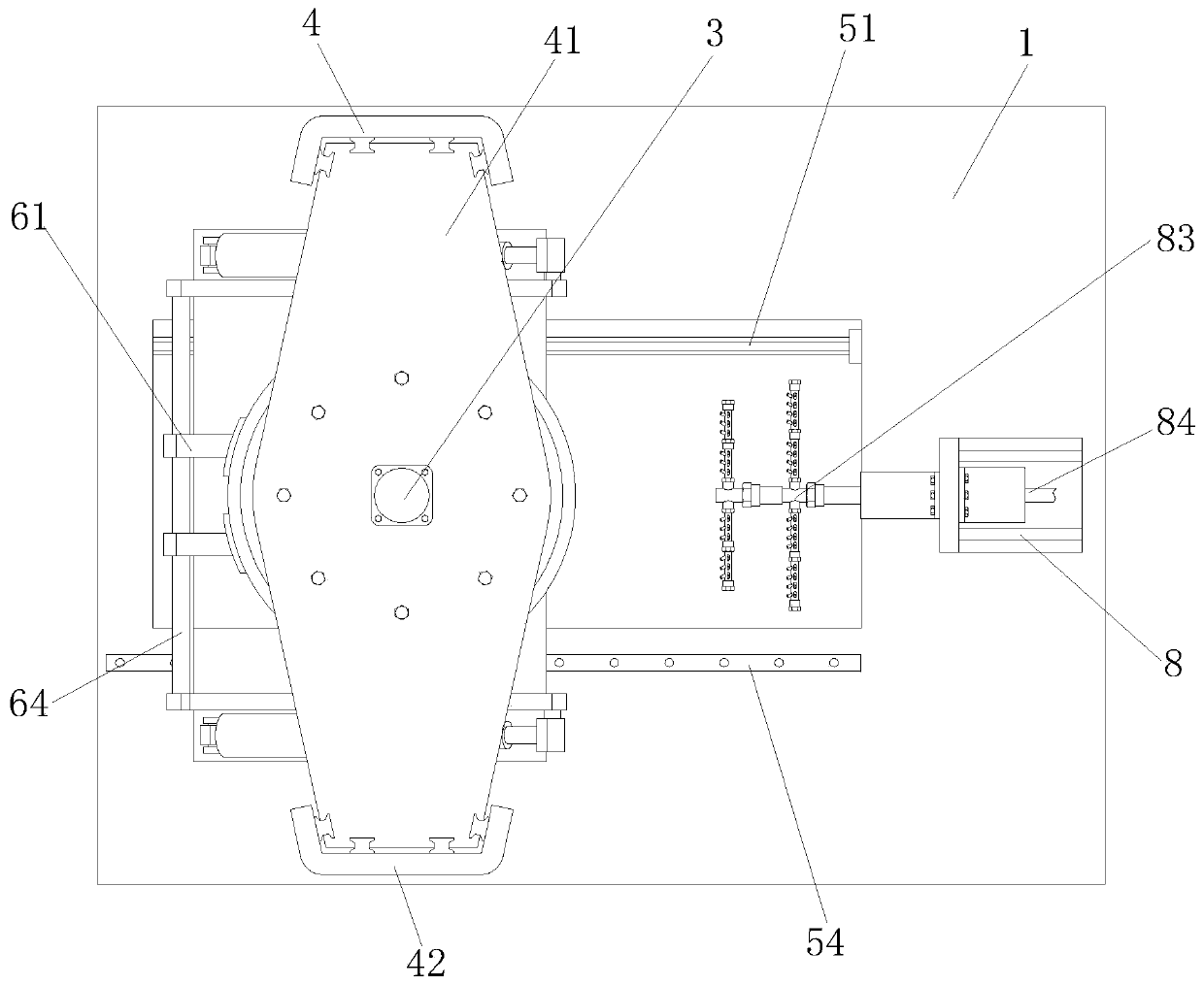
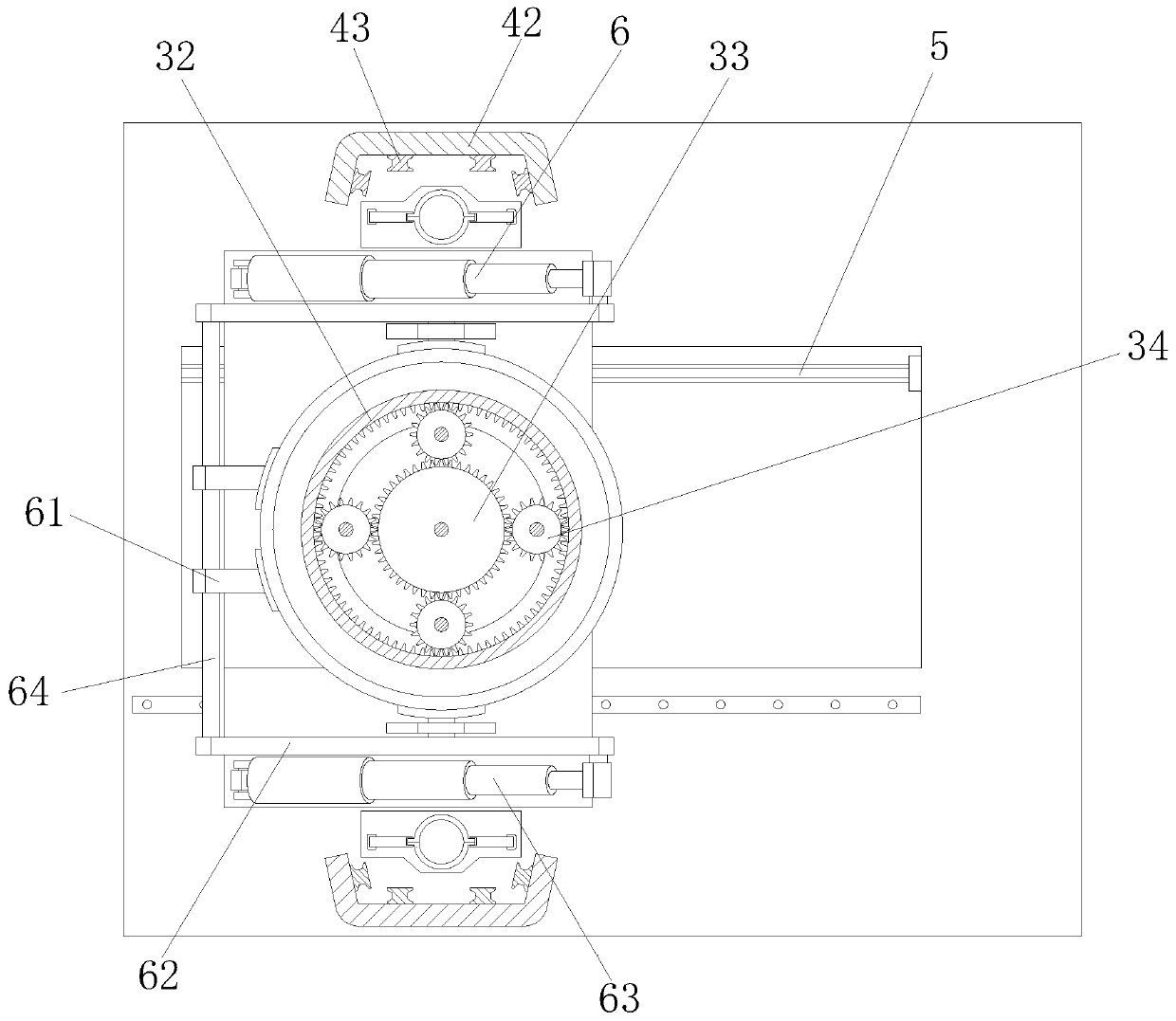
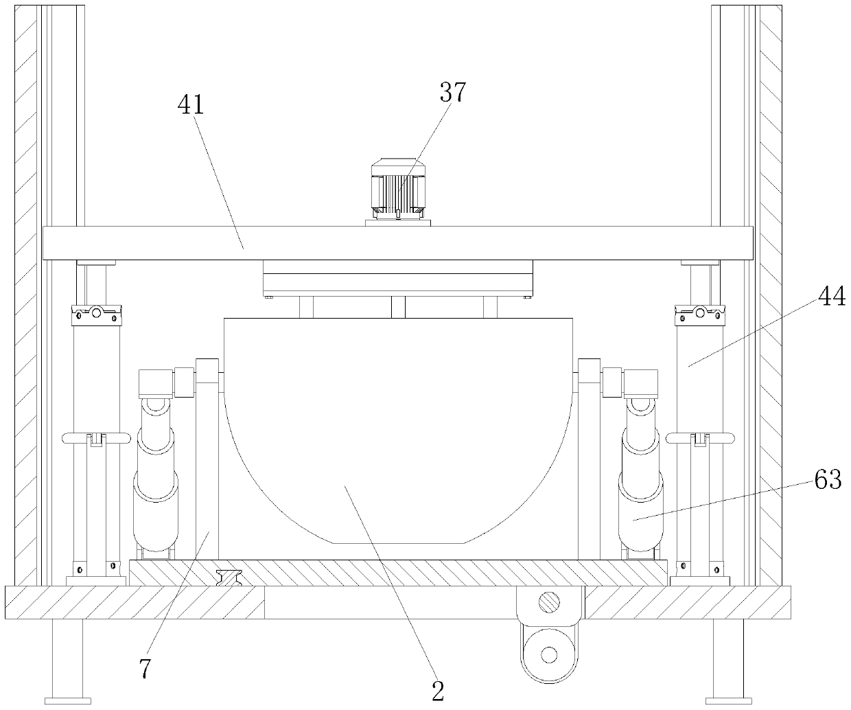
[0027] Such as Figure 1 to Figure 10 As shown, a magnesium oxide stirring device includes a bottom plate 1, a stirring tank 2 is distributed above the bottom plate 1, and a stirring mechanism 3 is distributed above the stirring tank 2, and a driving stirring mechanism is provided on the bottom plate 1 3 lifting and lowering mechanism 4, the mixing tank 2 is equipped with a No. 1 bracket 7 slidingly installed on the bottom plate 1, and the No. 1 bracket 7 is equipped...


PUM


Abstract

The invention relates to a magnesium oxide stirring device, which comprises a bottom plate, a stirring tank and a stirring mechanism distributed above the stirring tank, wherein a lifting mechanism for driving the stirring mechanism to lift is arranged on the bottom plate, the stirring tank is matched with a first bracket mounted on the bottom plate in a sliding manner, a unloading mechanism for driving the stirring tank to turn over so as to unload is installed on the first bracket, a cleaning device for cleaning the unloading residue in the stirring tank is arranged on the bottom plate, anda driving mechanism for driving the first bracket to move to the cleaning device in the length direction of the bottom plate is arranged on the bottom plate. According to the invention, the sun gear is matched with the planetary gears, so that the rotating shaft rotates around the axis of the sun gear so as to completely stir magnesium oxide; the swing rod is driven by the second hydraulic cylinder to swing, so that the stirring tank is driven to rotate so as to achieve the automatic unloading of the stirring tank; and the residue remained in the stirring tank is cleaned through the cleaning device, so that the fluidity of magnesium oxide during stirring is prevented from being influenced by excessive accumulation of the residue.

Description

technical field [0001] The invention relates to the field of stirring equipment, in particular to a magnesium oxide stirring device. Background technique [0002] The production of magnesium sulfate is usually realized by the reaction between magnesium oxide and dilute sulfuric acid. Before the reaction between magnesium oxide and dilute sulfuric acid, it is necessary to add water and stir the magnesium oxide before entering the reaction furnace for reaction. The traditional stirring is done by manually adding water, which is time-consuming, laborious and efficient. Low, the labor intensity of the workers is high, and the stirring is uneven for a long time, so that residues are generated during the reaction, resulting in a lot of time spent in cleaning the reaction furnace; the existing mixer needs to manually carry the mixing tank, and many workers are required during the handling process And the coordination of handling tools, the work efficiency is greatly reduced, manual...

Claims


Application Information

Patent Timeline
Patent Type & Authority Applications(China)
IPC IPC(8): B01F7/16B01F7/18B01F15/00B01F15/02
CPCB01F27/191B01F27/806B01F27/85B01F27/90B01F35/1453B01F35/75
Inventor 许俊林建果王兵许代发
Owner 芜湖市皖镁实业有限公司
Why Eureka
Try Eureka