LED dispensing equipment for light emitting diode manufacturing

A light-emitting diode and glue dispensing technology, which is applied to the surface coating liquid device, coating, etc., can solve the problems of reduced glue dispensing, valve pin or glue outlet damage, and empty points of the glue dispenser, etc., to improve Work efficiency, avoid clogging effect

Inactive Publication Date: 2020-04-10
江苏合泓通讯技术有限公司
View PDF0 Cites 8 Cited by
  • Summary
  • Abstract
  • Description
  • Claims
  • Application Information

AI Technical Summary

Problems solved by technology

[0004] 1. When the valve body is closed, the rebound of the large spring drives the valve needle to contact the glue outlet to break the glue. At this time, the valve needle will directly impact the glue outlet. After a long-term impact of the dispensing valve, the valve needle or the glue outlet will The glue port is damaged, resulting in incomplete glue breaking, and glue dripping and wire drawing during dispensing work
[0005] 2. Since the glue enters from top to bottom, the piston is in the process of rapid lifting. At this time, the glue has a downward movement speed, and a negative pressure appears at the valve, resulting in air bubbles or vacuum bubbles, resulting in empty space when the dispenser is working. Points and leaks affect production efficiency
[0007] 4. When using instant adhesive for dispensing work, it is easy to cause the glue to solidify in the needle, thereby blocking the glue and affecting the smoothness of dispensing and dispensing, resulting in a reduction in the dispensing amount, or even no glue, which seriously affects the point. Glue precision and quality

Method used


Image

  • LED dispensing equipment for light emitting diode manufacturing
  • LED dispensing equipment for light emitting diode manufacturing
  • LED dispensing equipment for light emitting diode manufacturing

Examples


Embodiment Construction

[0029] The following will clearly and completely describe the technical solutions in the embodiments of the present invention with reference to the accompanying drawings in the embodiments of the present invention. Obviously, the described embodiments are only some, not all, embodiments of the present invention. Based on the embodiments of the present invention, all other embodiments obtained by persons of ordinary skill in the art without making creative efforts belong to the protection scope of the present invention.

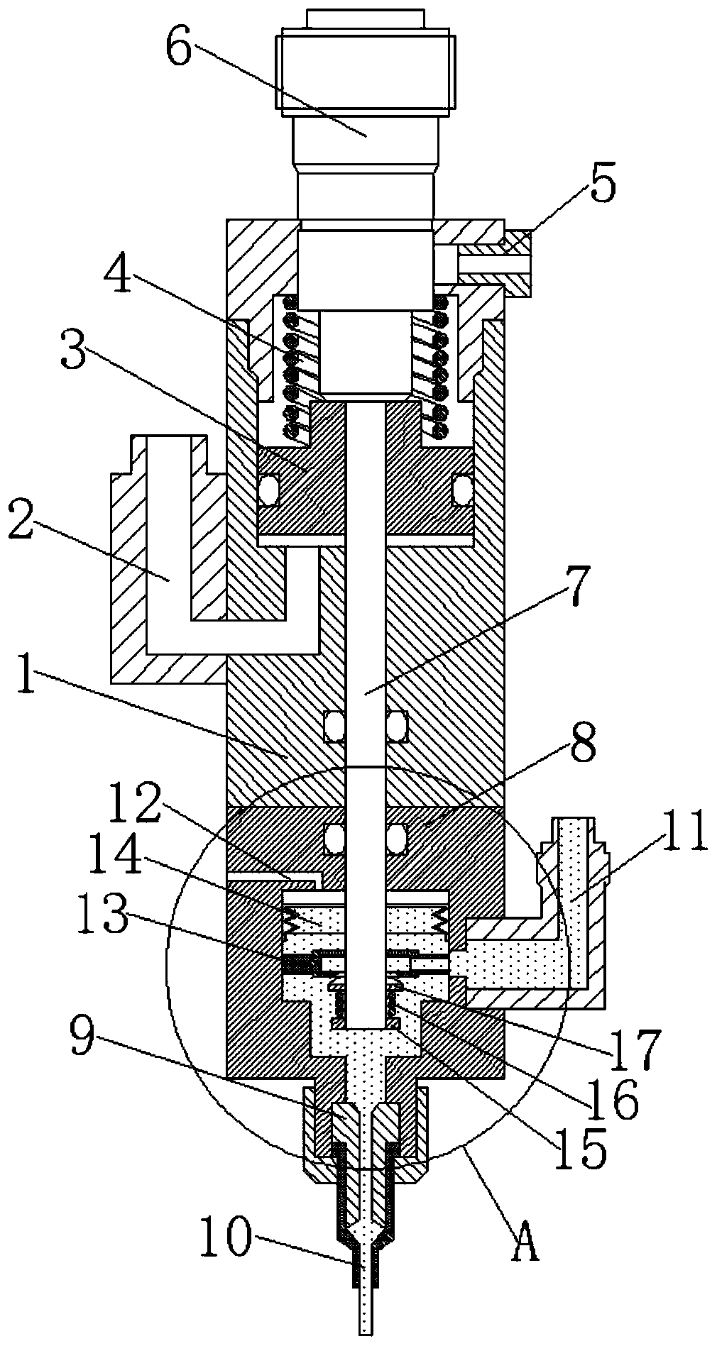
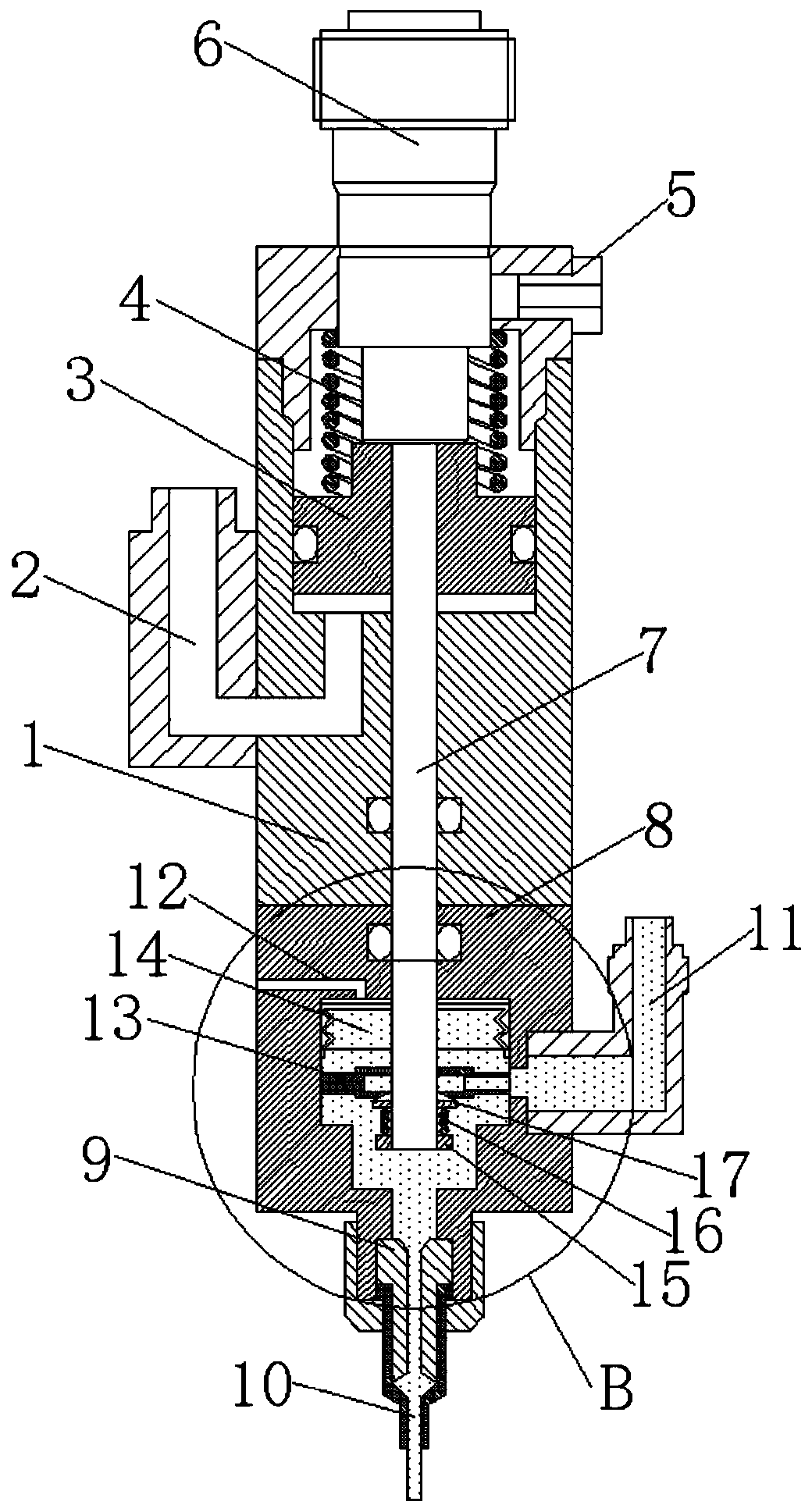
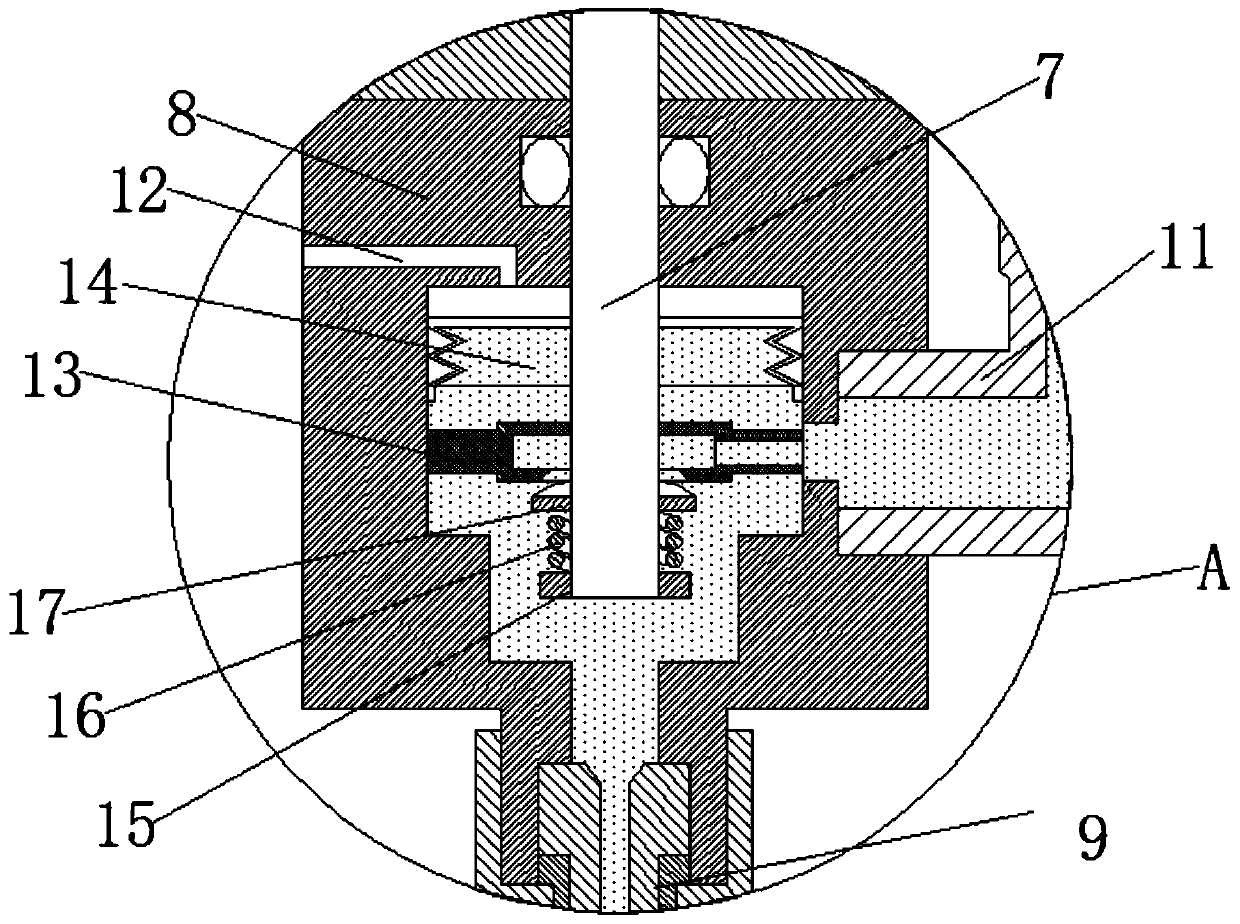
[0030] see Figure 1-7 , a kind of LED dispensing equipment for making light-emitting diodes, including an upper valve body 1, one side of the upper valve body 1 is fixedly connected with an air inlet 2, and the inner movable sleeve of the upper valve body 1 is connected with a piston 3, and the piston 3 The upper part of the valve body 1 is fixedly connected with a large spring 4, the upper part of the large spring 4 is fixedly connected with a fine-tuning kn...


PUM


Abstract

The invention relates to the technical field of dispensing equipment, and discloses LED dispensing equipment for light emitting diode manufacturing. The LED dispensing equipment comprises an upper valve body, one side of the upper valve body is fixedly connected with an air inlet, a piston is movably sleeved with the upper valve body, the upper part of the piston is fixedly connected with a largespring, and the upper part of the large spring is fixedly connected with a fine adjustment button, the upper portion of the other side of the upper valve body is fixedly connected with an air outlet,and a valve needle is fixedly connected to the bottom of the piston. The bottom of a capsule is fixedly and hermetically connected with a lower valve body, as the capsule is an elastic corrugated pipefitting, so that the valve needle drives the capsule to stretch in the process that the piston rapidly lifts to drive the valve needle to ascend, although the ascending displacement of the valve needle is small, stretching of the capsule can provide enough negative pressure to timely suck back a glue solution, the problem that negative pressure generated by ascending of the valve needle is insufficient is solved, timely back suction is guaranteed, and the situations of glue dripping and glue leakage are avoided.

Description

technical field [0001] The invention relates to the technical field of dispensing equipment, in particular to an LED dispensing equipment used for making light-emitting diodes. Background technique [0002] At present, dispensing machine equipment is commonly used for light-emitting diodes to dispens conductive silver glue and insulating glue. The dispensing valve is the most important work execution part in the dispensing machine. Plug type dispensing valve, diaphragm type dispensing valve, AB double liquid dispensing valve, and rotary dispensing valve, etc. Among them, the thimble type dispensing valve is more common, and its working principle is as follows: Figure 8 As shown: the glue barrel presses the glue from top to bottom from the glue inlet 11. When the valve of the glue inlet 11 is opened, the piston 3 drives the valve needle 7 to move upward under the push of the compressed gas to realize dispensing; When the valve of the glue inlet 11 is closed, the piston 3 is ...

Claims


Application Information

Patent Timeline
Patent Type & Authority Applications(China)
IPC IPC(8): B05C5/02B05C5/00
CPCB05C5/001B05C5/0208B05C5/0237
Inventor 许海明
Owner 江苏合泓通讯技术有限公司
Why Eureka
Try Eureka