Laser cleaning device and laser cleaning method

A laser cleaning and laser technology, applied in the laser field, can solve the problems of low cleaning efficiency of workpieces

Inactive Publication Date: 2020-04-10
HANS LASER TECH IND GRP CO LTD +1
View PDF5 Cites 6 Cited by
  • Summary
  • Abstract
  • Description
  • Claims
  • Application Information

AI Technical Summary

Problems solved by technology

[0003] Based on this, it is necessary to provide a laser cleaning device and a laser cleaning method for the problem of low workpiece cleaning efficiency.

Method used


Image

  • Laser cleaning device and laser cleaning method
  • Laser cleaning device and laser cleaning method
  • Laser cleaning device and laser cleaning method

Examples


Embodiment Construction

[0029] In order to facilitate the understanding of the present invention, the present invention will be described more fully below with reference to the associated drawings. Preferred embodiments of the invention are shown in the accompanying drawings. However, the present invention can be embodied in many different forms and is not limited to the embodiments described herein. On the contrary, the purpose of providing these embodiments is to make the disclosure of the present invention more thorough and comprehensive.

[0030] It should be noted that when an element is referred to as being “fixed” to another element, it can be directly on the other element or there can also be an intervening element. When an element is referred to as being "connected to" another element, it can be directly connected to the other element or intervening elements may also be present. The terms "vertical," "horizontal," "left," "right," and similar expressions are used herein for purposes of ill...


PUM


Abstract

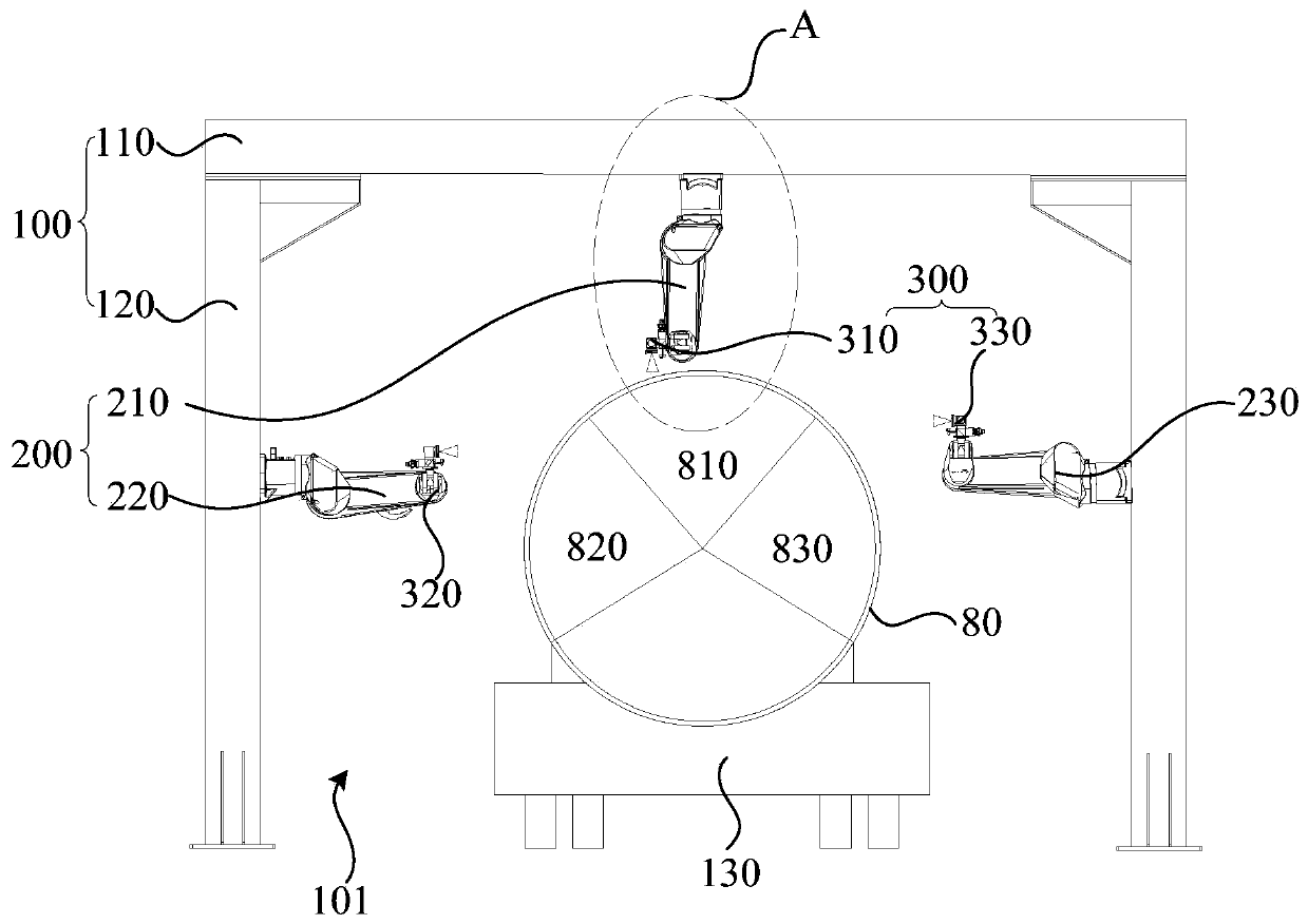
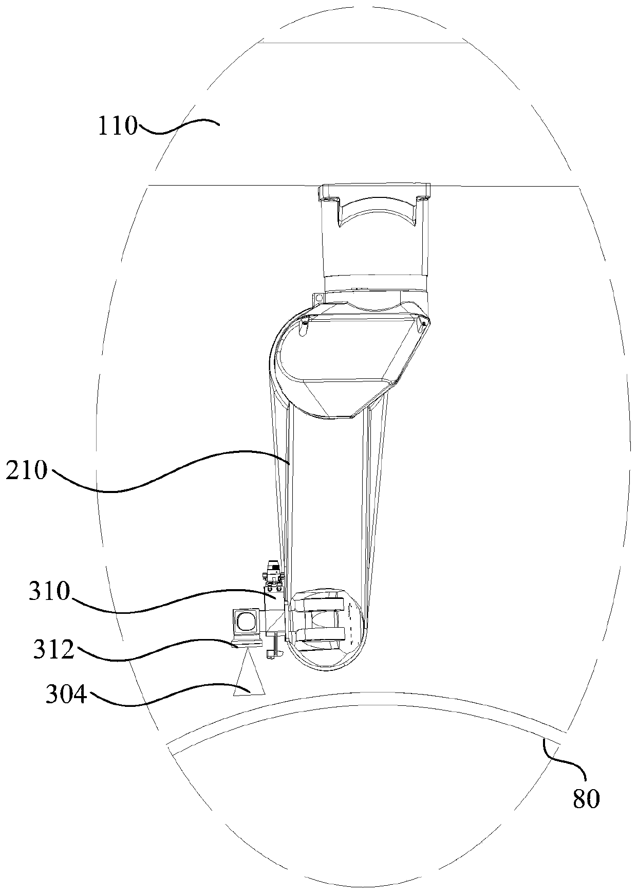
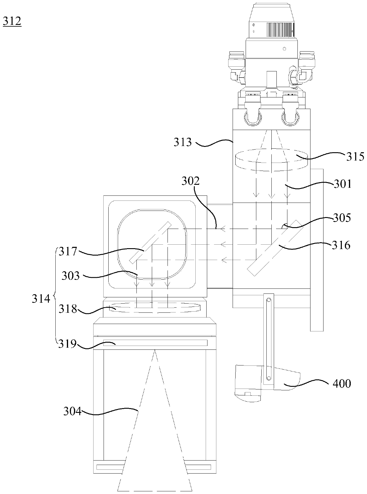
The invention relates to a laser cleaning device and a laser cleaning method. The laser cleaning device comprises a portal frame, a moving mechanism, and a laser cleaning mechanism; the portal framecomprises a cross beam and two upright columns, the cross beam is arranged between the two upright columns, and a workpiece is placed in a space formed by the cross beam and the two upright columns; the moving mechanism is arranged on the cross beam and/or the upright columns; and the laser cleaning mechanism is connected to the moving mechanism and used for emitting laser and cleaning different areas of the workpiece under the movement of the moving mechanism. The laser cleaning method comprises the following steps that the workpiece is placed in the portal frame; the laser cleaning mechanismis adopted to emit linear laser to irradiate the workpiece; and the laser cleaning mechanism cleans different areas of the workpiece under the movement of the moving mechanism. According to the lasercleaning device and the laser cleaning method, the laser cleaning mechanism can clean different areas of the workpiece under the movement of the moving mechanism, and the cleaning efficiency is high.

Description

technical field [0001] The invention relates to the field of laser technology, in particular to a laser cleaning device and a laser cleaning method. Background technique [0002] At present, during the production and use of the tanker, it is necessary to perform paint removal and cleaning on the surface of the tanker body. Existing methods mostly use manual mechanical polishing to remove rust, paint, oil, dust, etc. on the surface of the car body. The labor cost is high, and the cleaning efficiency is low. At the same time, a large amount of sewage will be generated, which is not conducive to environmental protection. Contents of the invention [0003] Based on this, it is necessary to provide a laser cleaning device and a laser cleaning method for the problem of low workpiece cleaning efficiency. [0004] A laser cleaning device for cleaning workpieces, comprising: [0005] The gantry frame includes a beam and two uprights, the beam is arranged between the two uprights,...

Claims


Application Information

Patent Timeline
Patent Type & Authority Applications(China)
IPC IPC(8): B08B7/00B23K26/064B23K26/067B23K26/08B23K26/70B23K26/142
CPCB08B7/0042B23K26/0643B23K26/067B23K26/0884B23K26/064B23K26/142B23K26/703
Inventor 麻明章王方何菊翠刘旭飞周桂兵陈焱高云峰
Owner HANS LASER TECH IND GRP CO LTD
Why Eureka
Try Eureka