Automatic stamping forming equipment for end part of cylindrical pipe fitting

A stamping forming and cylindrical technology, which is applied in the field of automatic stamping and forming equipment at the end of cylindrical pipe fittings, can solve the problems of trouble, waste of labor, low work efficiency, etc., and achieve the effect of reducing labor load, improving work efficiency and ensuring normal operation.

Inactive Publication Date: 2020-04-10
JILIN TEACHERS INST OF ENG & TECH
View PDF15 Cites 4 Cited by
  • Summary
  • Abstract
  • Description
  • Claims
  • Application Information

AI Technical Summary

Problems solved by technology

Instruments, household appliances, bicycles, office machinery, household utensils and other products also have a large number of stamped parts. After the stamping is completed, the processed parts will be engraved in the upper mold cavity, which needs to be taken out manually. It is more troublesome, and at the same time, a lot of labor is wasted in the process of continuous removal, and the work efficiency is relatively low. Therefore, we propose an automatic stamping and forming equipment for the end of cylindrical pipe fittings to solve the above problems.

Method used


Image

  • Automatic stamping forming equipment for end part of cylindrical pipe fitting
  • Automatic stamping forming equipment for end part of cylindrical pipe fitting
  • Automatic stamping forming equipment for end part of cylindrical pipe fitting

Examples


Embodiment Construction

[0018] The following will clearly and completely describe the technical solutions in the embodiments of the present invention with reference to the accompanying drawings in the embodiments of the present invention. Obviously, the described embodiments are only some, not all, embodiments of the present invention.

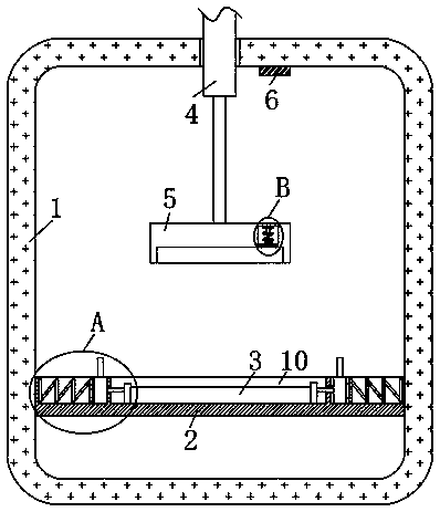
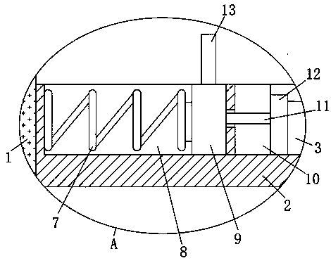
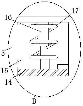
[0019] refer to Figure 1-2 , an automatic stamping and forming equipment for the end of a cylindrical pipe fitting, including a frame body 1, a stamping mechanism is provided through the upper end side wall of the frame body 1, and the stamping mechanism includes an electric push rod 4 that penetrates through the top of the frame body 1, and the electric push rod The telescoping end of the rod 4 is fixedly connected with a stamping die 5, a positioning cavity 15 is installed in the stamping die 5, a pushing mechanism is installed in the positioning cavity 15, and the pushing mechanism includes a second magnetic block 14 that is slidably connected on the inner side wa...


PUM


Abstract

The invention discloses automatic stamping forming equipment for an end part of a cylindrical pipe fitting, and relates to the technical field of automatic stamping equipment. The equipment comprisesa frame body, wherein a stamping mechanism is arranged on the side wall of the upper end of the frame body in a penetrating mode, a first magnetic block is mounted at the inner top of the frame body,a mounting plate is mounted on the inner side wall of the frame body, a placement groove is formed in the side wall of the upper end of the mounting plate, a to-be-machined piece is placed in the placement groove, sliding grooves are symmetrically formed in the side wall of the upper end of the mounting plate, clamping mechanisms are installed in the two sliding grooves, clamping rods are fixedlyconnected to the opposite ends of the two clamping mechanisms, through cooperative use among an electric push rod, a stamping die, the clamping rods, clamping plates, sliding blocks and a second spring, the stamping process of the to-be-machined piece is achieved, the situation that during the stamping process, the to-be-machined piece is shaken is effectively avoided, the stability of the to-be-machined piece is ensured, and the normal operation of the stamping process is guaranteed.

Description

technical field [0001] The invention relates to the technical field of automatic stamping equipment, in particular to an automatic stamping and forming equipment for the end of a cylindrical pipe fitting. Background technique [0002] Stamping forming refers to the process of applying external force to plates, strips, pipes and profiles by presses and molds to cause plastic deformation or separation, so as to obtain workpieces (stamping parts) of required shape and size. The blanks for stamping are mainly hot-rolled and cold-rolled steel sheets and strips. Among the steel products in the world, 60-70% are plates, most of which are stamped into finished products. The body, chassis, fuel tank, radiator fins of the car, the steam drum of the boiler, the shell of the container, the iron core silicon steel sheet of the motor and electrical appliances, etc. are all stamped. There are also a large number of stamped parts in products such as instruments, household appliances, bicy...

Claims


Application Information

Patent Timeline
Patent Type & Authority Applications(China)
IPC IPC(8): B21D22/02B21D43/00B21D45/04
CPCB21D22/025B21D43/003B21D45/04
Inventor 刘松青陈英李晓红邓俊
Owner JILIN TEACHERS INST OF ENG & TECH
Why Eureka
Try Eureka