

Automatic connection coupler for aerial rail vehicles
An automatic connection, aerial track technology, applied to the elevated railway system, railway vehicles, motor vehicles and other directions using suspended vehicles, can solve the problem of inconvenient operation of connection, achieve reliable connection and decoupling, realize intelligent operation, and facilitate standardization production effect
- Summary
- Abstract
- Description
- Claims
- Application Information
AI Technical Summary
Problems solved by technology
Method used
Image

Examples
Embodiment 1
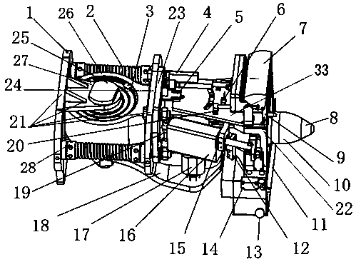
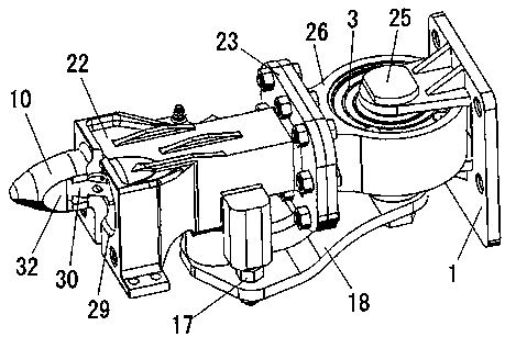
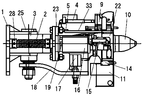
[0035] by attaching Figure 1-5 It can be seen that the present invention relates to an automatically connecting coupler for aerial rail vehicles, comprising a coupler head 10, a coupler body 22, a hook seat 23 and a buffer device 21, the coupler head 10 and the coupler body 22 are connected together, and are located on the coupler body 22, the hook body 22 is installed on the hook seat 23, and the hook seat 23 is installed on the buffer device 21; the hook head 10 is a conical rod-shaped body with a notch on the head, and through the cone and the notch Cooperate to form an automatic centering system; the coupler body 22 is provided with an automatic locking device and an automatic uncoupling system, and the coupling or uncoupling of the coupler is carried out through the automatic locking device and the automatic uncoupling system; the buffer The device 21 is a two-way buffer system, which absorbs the impact force when the coupler is connected, and controls the position of th...
Embodiment 2
[0048] The method of the second embodiment is basically the same as that of the first embodiment, except that the structure or position and size adopted are different; a kind of automatic coupling coupler for aerial rail vehicles, including a hook head, a hook body, a hook seat and a buffer device , the hook head and the hook body are connected together, located on the front end of the hook body, the hook body is installed on the hook seat, and the hook seat is installed on the buffer device; it is characterized in that: the hook head has a notch on the head The conical rod-shaped body forms an automatic centering system through the cooperation of the cone and the notch; the coupler body is provided with an automatic locking device and an automatic uncoupling system, and the coupling is carried out through the automatic locking device and the automatic uncoupling system. Connecting or uncoupling; the buffer device is a two-way buffer system, which absorbs the impact force when ...
PUM
 Abstract
Description
Claims
Application Information