Adjustable film pasting pad

An adjustable, film-sticking technology, applied in packaging and other directions, can solve the problems of inability to stick film, the backing plate cannot support the panel stably, and achieve the effect of simple structure

Inactive Publication Date: 2020-04-10
重庆布罗迪家具有限公司
View PDF6 Cites 2 Cited by
  • Summary
  • Abstract
  • Description
  • Claims
  • Application Information

AI Technical Summary

Problems solved by technology

[0004] However, since the length and width of the panel to be filmed have various specifications, if the backing plate of the same specification is used, such as when the area of ​​the panel is large, the area of ​​the backing plate is much smaller than that of the panel, so the backing plate cannot be applied to the panel. Stable support; for example, when the area of ​​the panel is small, the area of ​​the backing plate will be larger than the area of ​​the panel. Although the backing plate can provide stable support for the panel, although the bottom of the side of the panel will not be in contact with the workbench, but The bottom of the side of the panel will still be blocked by the backing plate, making it impossible to apply a one-time film to the side of the panel close to the backing plate

Method used


Image

  • Adjustable film pasting pad
  • Adjustable film pasting pad
  • Adjustable film pasting pad

Examples


Embodiment 1

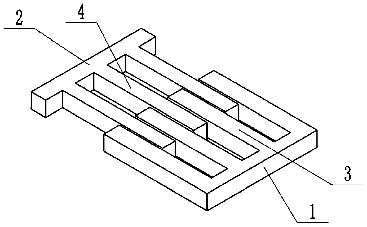
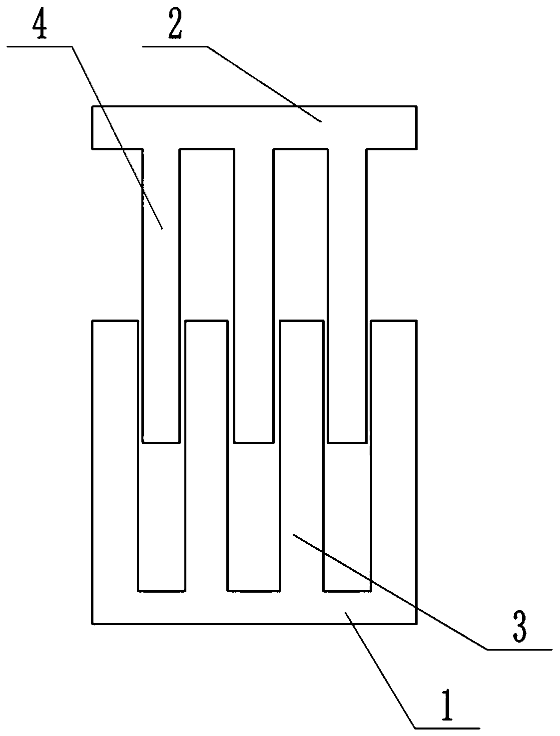
[0029] basically as attached Figure 1-Figure 2 Shown: an adjustable film pad, including a backing plate, the backing plate includes a first backing plate group 1 and a second backing plate group 2, the first backing plate group 1 is provided with a number of first comb teeth 3, this embodiment The number of the first comb teeth 3 is four, there is a first gap between the adjacent first comb teeth 3, and the second backing plate group 2 is provided with a plurality of second comb teeth 4. The number of the second comb teeth 4 is three, there is a second gap between the adjacent second comb teeth 4, the first comb teeth 3 are inserted in the second gap, and the second comb teeth 4 are inserted in the first gap , so that the first backing plate group 1 and the second backing plate group 2 can slide along the length direction of the first comb teeth 3 .

[0030] The specific implementation process is as follows: in this embodiment, the first comb teeth 3 are inserted into the se...

Embodiment 2

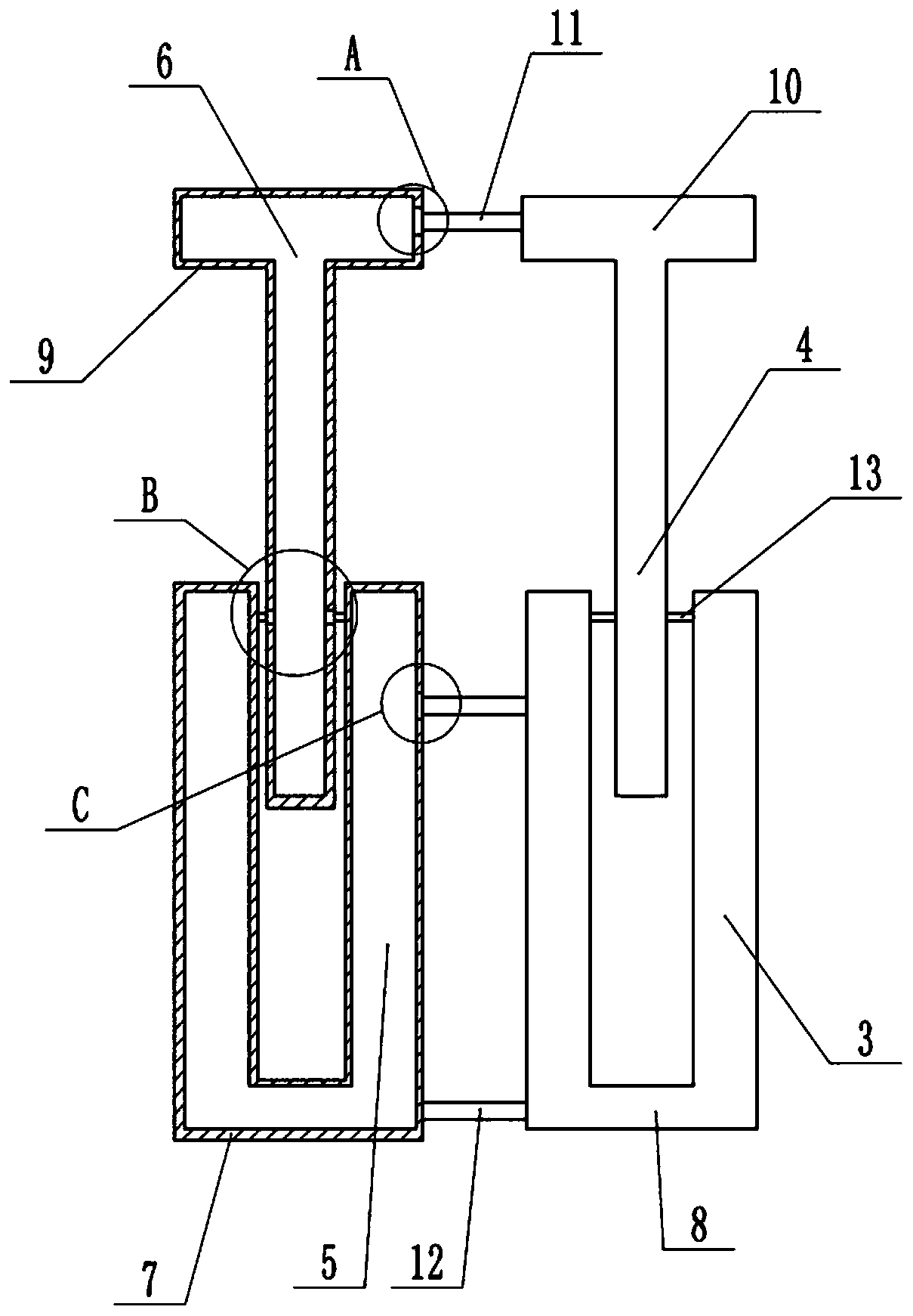
[0032] combine Figure 3-Figure 6 As shown in the figure, the inner walls of both sides of the first gap are provided with sliding grooves arranged along the length direction of the first comb teeth 3, and the side walls of the second comb teeth 4 are welded with sliding rods 13, and the sliding rods 13 are far away from the first comb teeth 4. One end of the second comb teeth 4 is inserted into the chute, so that the sliding rod 13 can slide relatively along the chute, so that through the cooperation of the sliding rod 13 and the chute, the first backing plate group 1 and the second backing plate group 2 The relative sliding between them is relatively smooth.

[0033] The first backing plate group 1 includes a first movable plate 7 and a second movable plate 8. The surface of the first movable plate 7 is provided with a first groove 5 for accommodating the second movable plate 8. The first groove 5 is located in the first movable plate 7. On a comb tooth 3, a first connectin...

Embodiment 3

[0037] combine Figure 7-Figure 9 As shown in the figure, the chute is provided with a number of card slots distributed in sequence along the length of the slot, the end of the sliding rod 13 away from the second comb teeth 4 is stuck in the card grooves, and the sliding rod 13 slides along the width direction of the second comb teeth 4 It is connected to the second comb teeth 4 . Specifically, the side walls of the second comb teeth 4 are provided with holes, and the sliding rods 13 pass through the holes, so that the sliding rods 13 can slide relative to the second comb teeth 4 . The second backing plate group 2 is provided with a control unit for controlling the sliding of the sliding rod 13 . The control unit includes a sliding block 19, a connecting rod 17, a first wedge block 20, a second wedge block 22, a compression spring 18, and a tension spring 21 for pulling the sliding rod 13 away from the slot. The tension spring 21 is connected to the two Between the ends of th...


PUM


Abstract

The invention relates to the field of panel film pasting, in particular to an adjustable film pasting pad. The adjustable film pasting pad comprises a pad plate. The pad plate comprises a first pad plate set and a second pad plate set. Multiple first comb teeth are arranged on the first pad plate set, and first clearances are arranged between the adjacent first comb teeth. Multiple second comb teeth are arranged on the second pad plate set, and second clearances are arranged between the adjacent second comb teeth. The first comb teeth are inserted into the second clearances, and the second comb teeth are inserted into the first clearances. The first pad plate set and the second pad plate set can slide in the length direction of the first comb teeth. By means of the scheme, the adjustable film pasting pad can adapt to panels of different specifications.

Description

technical field [0001] The invention relates to the field of panel sticking, in particular to an adjustable sticking pad. Background technique [0002] After the panel is processed, it is necessary to affix a layer of film on the top of the panel, so as to protect the panel and make the appearance of the panel more beautiful. Put the film on the side of the panel. Since the panel is directly placed on the workbench, the side of the panel close to the workbench is difficult to be filmed because it is close to the workbench. If the side of the panel is to be close to the workbench When the film is attached, it is necessary to separate the panel from the worktable, so that additional filming is performed on the side of the panel close to the worktable, but this operation is troublesome. [0003] In order to solve the above-mentioned technical problems, in the prior art, when filming the panel, it is necessary to place a backing plate below the panel with a smaller area than th...

Claims


Application Information

Patent Timeline
IPC IPC(8): B65B33/02
CPCB65B33/02
Inventor 郑登卫
Owner 重庆布罗迪家具有限公司
Why Eureka
Try Eureka