
A boring machine and its muck transportation device

A technology of transportation device and roadheader, which is used in transportation and packaging, underground transportation, shaft equipment, etc., can solve the problems of blockage of transportation pipelines, easy backflow of slag, and unsuitable use.

Active Publication Date: 2020-06-26
CHINA RAILWAY CONSTR HEAVY IND
View PDF16 Cites 0 Cited by
  • Summary
  • Abstract
  • Description
  • Claims
  • Application Information

AI Technical Summary

Problems solved by technology

[0003] The existing vertical shaft slag conveying device slurries the slag and then pumps the slag out. In practical applications, it is easy to cause blockage of the transportation pipeline, and the slag is easy to flow back, so it is not suitable for use in places with a lot of gravel.

Method used


Image

  • A boring machine and its muck transportation device
  • A boring machine and its muck transportation device
  • A boring machine and its muck transportation device

Examples


Embodiment Construction

[0026] The following will clearly and completely describe the technical solutions in the embodiments of the present invention with reference to the accompanying drawings in the embodiments of the present invention. Obviously, the described embodiments are only some, not all, embodiments of the present invention. Based on the embodiments of the present invention, all other embodiments obtained by persons of ordinary skill in the art without making creative efforts belong to the protection scope of the present invention.

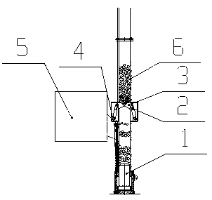
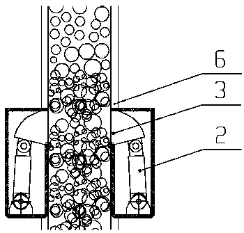
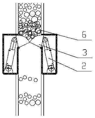
[0027] Please refer to Figure 1~5 , figure 1 It is a schematic diagram of the structure of the muck transport device in working state; figure 2 It is a partial structural schematic diagram of the muck transportation device; image 3 It is a structural schematic diagram of the first gate in an open state; Figure 4 It is a structural schematic diagram of the first type of gate in a closed state; Figure 5 It is a structural schematic diagram of the second...


PUM


Abstract

The invention discloses a roadheader and a muck transportation device thereof. The muck transportation device includes a transportation passage for conveying the muck. There is a push mechanism inside the transport channel for pushing the muck out of the gate assembly, and the gate assembly is used to close when the push mechanism is away from the gate assembly to avoid backflow of the muck; the side wall of the transport channel is provided with a gap, the gate The components include gates arranged in the relief gap, and a gate driving mechanism arranged outside the transportation channel and used to drive the gates to move. The muck transportation device provided in the present application uses a gate assembly to block the transportation channel, thereby preventing the muck from flowing back through the gate assembly and ensuring normal transportation of the muck.

Description

technical field [0001] The invention relates to the technical field of shaft construction, and more specifically, relates to a muck transportation device. In addition, the present invention also relates to a roadheader comprising the above-mentioned muck transportation device. Background technique [0002] During the excavation of the vertical shaft, the muck is conveyed from the excavation surface to the tail of the shield through the screw conveyor, and is conveyed to the muck upward transportation channel through the muck storage device, and then the muck is transported upward to the vertical belt conveyor, and then by the vertical The belt conveyor is transported to the ground. During the upward transportation of the muck, how to transport the muck from the tail of the shield to the vertical belt conveyor is the key to transporting the muck out, so it is particularly important to ensure the efficient upward transportation of the muck. [0003] The existing shaft slag c...

Claims


Application Information

Patent Timeline
Patent Type & Authority Patents(China)
IPC IPC(8): E21D1/03E21F13/00E21D9/12B65G65/44
CPCB65G65/44E21D1/03E21D9/12E21F13/00
Inventor 刘飞香刘在政彭正阳李培李德平姚满杨楚戈任庆成邓金涛刘兴敬运红丁张飞
Owner CHINA RAILWAY CONSTR HEAVY IND
Learn More