
A high-rise building fire safety power supply equipment

A technology for high-rise buildings and power supply equipment, applied in mechanical equipment, sustainable buildings, wind power generation, etc., can solve problems such as reducing the utilization rate of high-rise building platforms, power supply equipment without external compensation, and fire safety problems in high-rise buildings. The effect of power blank period, novel structure and simple structure

Active Publication Date: 2021-10-01
DAMING TECH
View PDF6 Cites 0 Cited by
  • Summary
  • Abstract
  • Description
  • Claims
  • Application Information

AI Technical Summary

Problems solved by technology

[0002] With the development of society and the advancement of science and technology, high-rise buildings are loved by people. They occupy a small area and have a large volume, which is especially suitable for commercial and residential buildings. However, due to the large number of users in high-rise buildings, they consume a lot of electricity. , special power distribution equipment is required, and the existing power supply equipment does not have external compensation, so a large amount of power supply is required, which will bring a lot of burden to the power supply network of high-rise buildings, and even cause high-rise building fire protection in extreme cases. Safety issues, and the roof area of ​​high-rise buildings is open, and its height is high, so the wind is strong, which is very suitable for wind power generation. However, due to the limitation of equipment volume in existing high-rise buildings, the utilization rate of high-rise building platforms has been reduced. In view of this, After in-depth research on the above problems, this case came into being

Method used


Image

  • A high-rise building fire safety power supply equipment
  • A high-rise building fire safety power supply equipment
  • A high-rise building fire safety power supply equipment

Examples


Embodiment

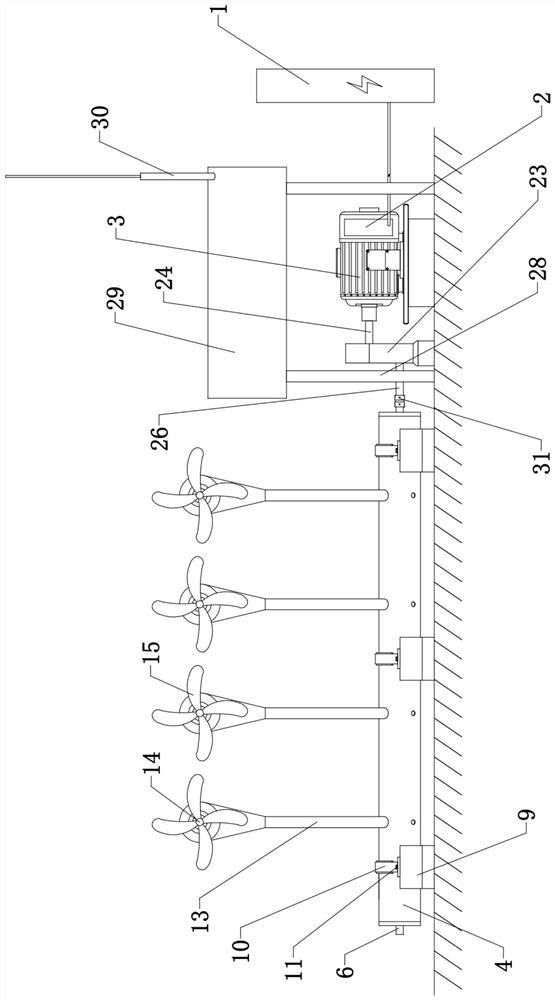
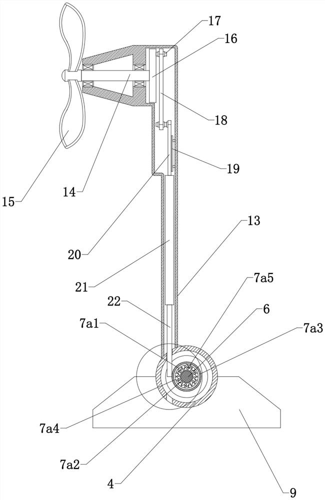
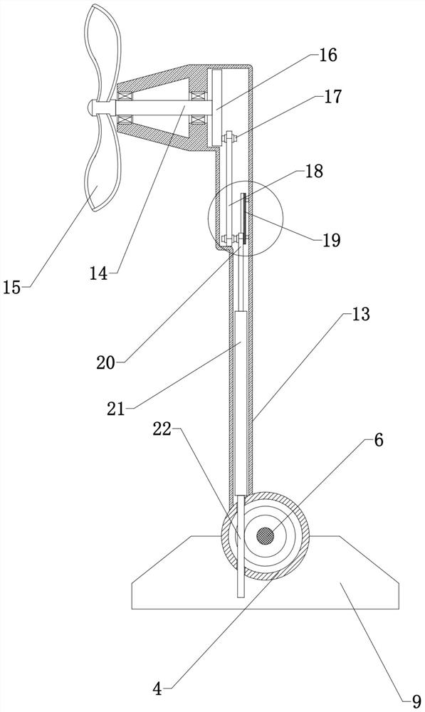
[0039] Embodiment: according to specification Figure 1-10 It can be seen that this case is a high-rise building fire safety power supply equipment, including a backup power supply 1, a voltage stabilizer 2 and a generator set 3, the generator set 3 is installed on the roof, the generator set 3 is connected to a wind power generation unit, and the voltage stabilizer 2 is installed on the On the generator set 3, the backup power supply 1 is installed in the building and connected to the voltage stabilizer 2. In the specific implementation process, the partial energy is converted into mechanical energy through the wind power generation unit, and the mechanical energy is converted into electrical energy through the generator set 3, thereby undergoing voltage stabilization. The regulator 2 stabilizes the voltage and stores the electric energy in the backup power supply 1, which effectively relieves the pressure on the power supply of high-rise buildings;

[0040] The wind power ge...


PUM


Abstract

The invention discloses a high-rise building fire safety power supply equipment, including a backup power supply, a voltage stabilizer and a generator set, the generator set is installed on the roof, the generator set is connected with a wind power generation unit, and the voltage stabilizer is installed on the On the generator set, the backup power supply is installed in the building and connected to the voltage stabilizer; the beneficial effect of the present invention is that the power supply equipment for high-rise buildings has a novel structure, fully utilizes the advantage of strong wind at high places, and converts existing wind power The equipment is miniaturized to meet the conditions for installation on the roof. Using the principle of connecting rods and one-way ratchets respectively, multiple groups of wind-driven structures are connected in parallel to accelerate and rotate a main shaft, so that the output speed is faster and the gap between them is filled. During the power blank period between them, it can provide stable speed output to drive the generator set, which not only makes full use of the roof space and wind energy, but also has the advantages of simple structure, convenient installation and production.

Description

technical field [0001] The invention relates to the technical field of new energy sources for high-rise buildings, in particular to fire safety power supply equipment for high-rise buildings. Background technique [0002] With the development of society and the advancement of science and technology, high-rise buildings are loved by people. They occupy a small area and have a large volume, which is especially suitable for commercial and residential buildings. However, due to the large number of users in high-rise buildings, they consume a lot of electricity. , special power distribution equipment is required, and the existing power supply equipment does not have external compensation, so a large amount of power supply is required, which will bring a lot of burden to the power supply network of high-rise buildings, and even cause high-rise building fire protection in extreme cases. Safety issues, and the roof area of ​​high-rise buildings is open, and its height is high, so th...

Claims


Application Information

Patent Timeline
Patent Type & Authority Patents(China)
IPC IPC(8): F03D9/25F03D9/45F03D15/00F03D13/20F03D80/00F16H1/06
CPCF16H1/06F03D9/25F03D9/45F03D13/20F03D15/00F03D80/00Y02B10/30Y02E10/72Y02E10/728Y02P70/50
Inventor 童建明朱文玲
Owner DAMING TECH
Learn More