Stepless speed changing device with speed adjusting component arranged inside

A continuously variable transmission device and speed regulation technology, which is applied in the direction of control devices, transmission devices, vehicle components, etc., can solve problems such as structural size and weight that cannot be solved, and achieve the effect of optimizing the efficiency of all working conditions

Active Publication Date: 2020-04-10
杭州肇鹏科技有限公司
View PDF8 Cites 1 Cited by
  • Summary
  • Abstract
  • Description
  • Claims
  • Application Information

AI Technical Summary

Problems solved by technology

However, the structural size and weight defects

Method used


Image

  • Stepless speed changing device with speed adjusting component arranged inside
  • Stepless speed changing device with speed adjusting component arranged inside
  • Stepless speed changing device with speed adjusting component arranged inside

Examples


Embodiment 1

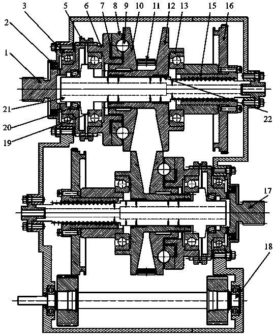
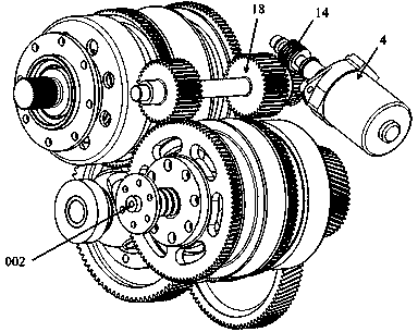
[0059] Further explanation in conjunction with the accompanying drawings: In this embodiment, there are two power coupling shafts: power coupling shaft I and power coupling shaft II, and they are coaxial with the cone-disc shaft system I and the cone-disk shaft system II respectively, such as Figure 1-4 The continuously variable transmission device built in the speed regulating components shown includes the cone shaft system I 001, the cone shaft system II 002, the speed control shaft system 18, the power coupling shaft I 1 and the power coupling shaft II17.

[0060] In this embodiment, the power coupling axis I 1 is coaxial with the cone shaft system I, and the power coupling shaft II 17 is coaxial with the cone shaft system I.

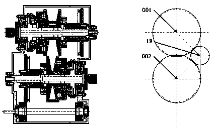
[0061] Such as Figure 2-4 As shown, the speed regulating shaft system is arranged between the two cone-disk shaft systems and in the cross-section of the three shaft systems, the three shafts are arranged in a triangle. The cone-disk shaft system I...

Embodiment 2

[0092] Such as Figure 5 As shown, the difference from Embodiment 1 is that the power coupling shaft of this embodiment is not coaxial with the cone-disc shaft system I and the cone-disk shaft system II, and the pressurization mechanism of this embodiment includes a set of pressurization springs 24. One end of the pressure spring 24 is pressed on the fixed cone 10, and the other end is pressed on the spring seat 6.

Embodiment approach

[0094] Dynamically coupled axes can be set in the following different ways:

[0095] Power coupling axis 1 is connected to the spring seat:

[0096] The power coupling shaft 1 is not coaxial with the speed regulating screw 21, and the power coupling shaft 1 and the spring seat are connected through gear meshing or a chain. The chain is preferably a toothed chain, preferably a toothed silent chain.

[0097] The power coupling shaft 1 is coaxial with the speed regulating screw 21, and the power coupling shaft 1 is connected to the spring seat 6 through a spline.

[0098] The power coupling shaft 1 is coaxial with the speed regulating screw 21. The power coupling shaft 1 and the spring seat 6 are connected through the axially slidable spline sleeve 5. The spline sleeve 5 can slide axially to different positions, and the power coupling can be coupled or decoupled. Power between shaft 1 and spring seat 6. The splined sleeve 5 is preferably driven by an electric motor.

[0099] T...


PUM


Abstract

The invention belongs to the field of power machine speed changers, and particularly relates to a stepless speed changing device with a speed adjusting component arranged inside. The speed adjusting component is arranged in a conical disc shaft sleeve, so that the axial distance of the stepless speed changing device is reduced; and compared with arrangement of the speed adjusting component outsidethe conical disc shaft sleeve, cost is reduced, and efficiency is improved.

Description

technical field [0001] The invention belongs to the field of power mechanical transmissions, in particular to a cone-disc continuously variable transmission, more specifically to a cone-disk continuously variable transmission with a speed regulating component built into the cone. Background technique [0002] Since the beginning of the 21st century, a series of electromechanical control cone-disc continuously variable transmissions have gradually matured, and have been widely used in road, off-road vehicles and general machinery due to their low cost, high efficiency and high reliability. In particular, its adaptability to pure electric driving conditions has prompted its gradual application in electric vehicles. [0003] The main system function of the cone-disk continuously variable transmission is to ensure the transmission of power, to pressurize the friction pair of the cone-disk and the flexible transmission element, and to adjust the speed of the axial distance betwee...

Claims


Application Information

Patent Timeline
IPC IPC(8): F16H9/18F16H37/02F16H63/30B60K17/02B60K17/08B60K17/16
CPCB60K17/02B60K17/08B60K17/16F16H9/18F16H37/021F16H63/30F16H2037/025
Inventor 不公告发明人
Owner 杭州肇鹏科技有限公司
Why Eureka
Try Eureka