A combined diverter valve based on thread transmission control

A threaded drive, combined technology, applied in valve details, valve devices, multi-port valves, etc., can solve the problems of affecting the control effect of the valve core, affecting the sealing effect, and not having a long service life, so as to improve the service life and practicability. , Improve the blocking effect, improve the effect of the sticking effect

Active Publication Date: 2021-12-24
维克托阀门集团有限公司
View PDF5 Cites 0 Cited by
  • Summary
  • Abstract
  • Description
  • Claims
  • Application Information

AI Technical Summary

Problems solved by technology

[0003] The traditional diverter valve mainly realizes the cut-off and diversion of the fluid by rotating the spool at the connection between the main flow and the diversion. In order to achieve the cut-off effect of the spool, the spool must be in close contact with the pipe wall. During the process, the valve core will be worn, and after long-term use, it will affect the control effect of the valve core, and it is prone to leakage. The service life is not long, and the valve core will undergo cold and heat deformation, which will affect its sealing effect and make the valve shell The body expands and cracks, the temperature range that can adapt to the fluid is small, and the practicability is reduced, and the diversion valve will have different diversion pipes, and impurities are easy to accumulate at the connection between the diversion pipe and the main pipe and cause blockage. When dredging, the connection between the valve and the pipeline needs to be disconnected first, and then reconnected after the cleaning is completed. The operation is cumbersome and time-consuming

Method used


Image

  • A combined diverter valve based on thread transmission control
  • A combined diverter valve based on thread transmission control
  • A combined diverter valve based on thread transmission control

Examples


Embodiment Construction

[0023] The following will clearly and completely describe the technical solutions in the embodiments of the present invention with reference to the accompanying drawings in the embodiments of the present invention. Obviously, the described embodiments are only some, not all, embodiments of the present invention. Based on the embodiments of the present invention, all other embodiments obtained by persons of ordinary skill in the art without making creative efforts belong to the protection scope of the present invention.

[0024] The embodiment of the combined diverter valve based on thread transmission control is as follows:

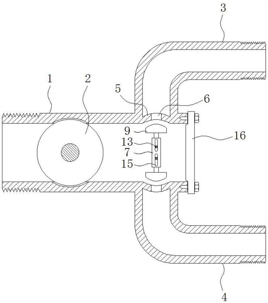
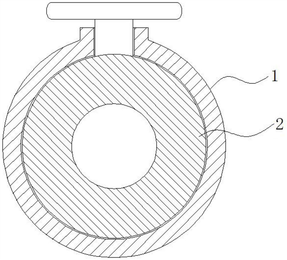
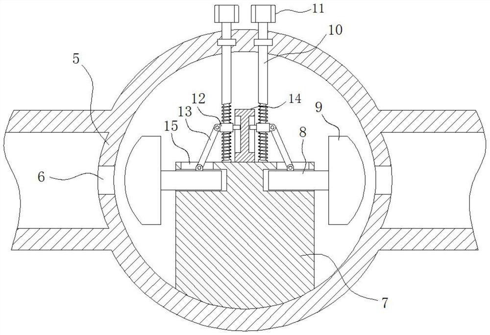
[0025] see Figure 1-4 , a combined diverter valve based on screw transmission control, including water inlet pipe 1, ball valve 2, upper water outlet pipe 3, lower water outlet pipe 4, partition plate 5, round hole 6, mounting plate 7, telescopic rod 8, plunger 9 , threaded rod 10, nut head 11, slide block 12, connecting rod 13, limit column 14, limit g...


PUM


Abstract

The invention provides a combined diverter valve based on thread transmission control, which relates to the technical field of valves. The combined diverter valve based on thread transmission control includes a water inlet pipe, a ball valve is slidably connected inside the water inlet pipe, and an upper water outlet pipe and a lower water outlet pipe are respectively connected to the upper and lower sides of the right end of the water inlet pipe. A dividing plate is fixedly installed at the joints of the water outlet pipe, the lower water outlet pipe and the water inlet pipe, and a circular hole is provided in the center of the dividing plate. The combined shunt valve based on thread transmission control avoids the wear caused by the mutual attachment of the traditional valve core and the pipe wall, and the damage to the valve and control effect caused by the thermal expansion and contraction of the valve core, and improves the service life of the valve. And practicability, when cleaning foreign matter inside the valve or replacing the plunger, it is not necessary to disconnect the valve from the pipeline, just open the sealing plate directly, the operation is simpler, saving time and effort.

Description

technical field [0001] The invention relates to the technical field of valves, in particular to a combined diverter valve based on thread transmission control. Background technique [0002] Valves are pipeline accessories used to open and close pipelines, control flow direction, adjust and control the parameters of the conveying medium. According to its function, it can be mainly divided into shut-off valve, check valve, regulating valve, etc., which are the control components in the fluid delivery system, with functions of cut-off, adjustment, flow diversion, reverse flow prevention, voltage stabilization, diversion or overflow pressure relief, etc. There are many varieties and specifications of valves used in fluid control systems, and diverter valves are one of them. [0003] The traditional diverter valve mainly realizes the cut-off and diversion of the fluid by rotating the spool at the connection between the main flow and the diversion. In order to achieve the cut-off...

Claims


Application Information

Patent Timeline
Patent Type & Authority Patents(China)
IPC IPC(8): F16K11/22F16K31/50F16K11/00F16K27/00
CPCF16K11/22F16K31/50F16K11/00F16K27/00
Inventor 楼奇杰
Owner 维克托阀门集团有限公司
Why Eureka
Try Eureka