Electromagnetic energy water heater

An electromagnetic energy water heater and transducer technology, applied in fluid heaters, chemical instruments and methods, lighting and heating equipment, etc., can solve problems such as easy accumulation of scale, affect heating efficiency, and service life of effluent quality, so as to prevent Accumulation of scale, avoiding the risk of electric leakage, and the effect of preventing accumulation

Pending Publication Date: 2020-04-10
胡家华
0 Cites 0 Cited by

AI-Extracted Technical Summary

Problems solved by technology

However, after long-term use, scale is easy to accumulate in the water ...

Method used

Because the metal heating element 110 is positioned in the thermal insulation layer 120, it can prevent the heat generated by the metal heating element 110 from distributing under the action of electromagnetic induction, which is conducive to making the heat generated by the metal heating element 110 more conductive to the water flow, improving the energy utilization. The heat insulation layer 120 may be formed of materials such as polyurethane foam or asbestos.
Glass tube 121 has good heat resistance, is suitable for coordinating metal heating element 110 work, and glass tube 121 has excellent corrosion resistance, can not produce impact on water quality, and service life is long, and the intensity of glass tube 121 is high simultaneously , can cope with the pressure from inside and outside, and improve the stability of the structure. In addition, a glass fiber layer 122 is provided outside the glass tube 121, which can further improve the heat insulation performance and is beneficial to further improve the heating efficiency.
In some embodiments, the metal heating element 110 can be provided with an insulating layer on the surface, and an anion temperature-sensitive paint layer is arranged outside the insulating layer, although the voltage of the eddy current generated by the metal heating element 110 under the action of electromagnetic induction will not It is very high and will not cause danger to the use...

Abstract

The invention discloses an electromagnetic energy water heater. The electromagnetic energy water heater comprises a water pipe, a metal heating piece arranged in the water pipe, a magnet exciting coilwound around the outer surface of the water pipe, an alternating current signal generating unit electrically connected with the magnet exciting coil, and an ultrasonic transducer arranged on the water pipe, and the alternating current signal generating unit is electrically connected with the ultrasonic transducer. The alternating current signal generating unit generates alternating current signals to be transmitted to the magnet exciting coil, under the effect of the alternating current signals, the magnet exciting coil generates a changing magnetic field, the metal heating piece generates aneddy current in the changing magnetic field due to electromagnetic induction, and thus the metal heating piece generates heat to heat a water flow in the water pipe. In addition, the alternating current signal generating unit can also transmit the alternating current signals to the ultrasonic transducer, the ultrasonic transducer generates an ultrasonic wave under driving of the alternating current signals, the ultrasonic wave is conducted on the water pipe, and thus scale on the water pipe can be removed so as to prevent accumulation of the scale.

Application Domain

Technology Topic

Image

  • Electromagnetic energy water heater
  • Electromagnetic energy water heater
  • Electromagnetic energy water heater

Examples

  • Experimental program(1)

Example Embodiment

[0022] This section will describe the specific embodiments of the present invention in detail. The preferred embodiments of the present invention are shown in the drawings. The function of the drawings is to supplement the description of the text part of the manual with graphics, so that people can intuitively and vividly understand the text. Each technical feature and overall technical solution of the invention cannot be understood as a limitation on the protection scope of the present invention.
[0023] In the description of the present invention, it should be understood that the orientation description involved, such as up, down, front, back, left, right, etc., indicates the orientation or positional relationship based on the orientation or positional relationship shown in the drawings, and only In order to facilitate the description of the present invention and simplify the description, it does not indicate or imply that the pointed device or element must have a specific orientation, be configured and operate in a specific orientation, and therefore cannot be understood as a limitation to the present invention.
[0024] In the description of the present invention, several means one or more, multiple means two or more, greater than, less than, exceeding, etc. are understood to not include the number, and above, below, and within are understood to include the number. If it is described that the first and second are only used for the purpose of distinguishing technical features, and cannot be understood as indicating or implying relative importance or implicitly specifying the number of the indicated technical features or implicitly specifying the order of the indicated technical features relationship.
[0025] In the description of the present invention, unless otherwise clearly defined, terms such as setting, installation, and connection should be understood in a broad sense, and those skilled in the art can reasonably determine the specific meaning of the above terms in the present invention in combination with the specific content of the technical solution.
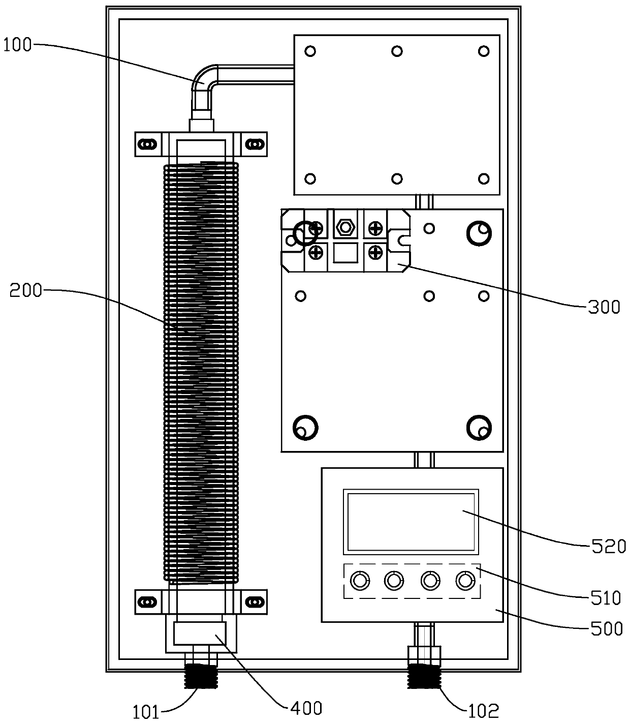
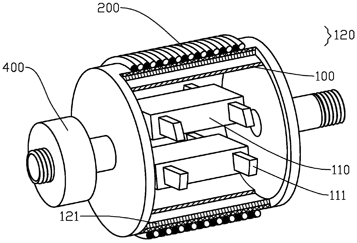
[0026] Reference Figure 1 to Figure 4 , The electromagnetic water heater provided by the present invention includes: a water pipe 100; a metal heating element 110 arranged in the water pipe 100; an excitation coil 200 wound on the outer surface of the water pipe 100; an AC signal generating unit 300 electrically connected to the excitation coil 200 Sexual connection; the ultrasonic transducer 400 is arranged on the water pipe 100, and the AC signal generating unit 300 is electrically connected to the ultrasonic transducer 400.
[0027] The AC signal generating unit 300 generates an AC signal and transmits it to the excitation coil 200. Under the action of the AC signal, the excitation coil 200 generates a changing magnetic field. The metal heating element 110 generates eddy current due to electromagnetic induction in the changing magnetic field, and the metal heating element 110 Heat is generated to heat the water flow in the water pipe 100. In addition, the AC signal generating unit 300 can also transmit AC signals to the ultrasonic transducer 400. The ultrasonic transducer 400 is driven by the AC signal to generate ultrasonic waves and conduct on the water pipe 100, which can remove the scale on the water pipe 100, thereby preventing the scale. Of accumulation. Through the above method, the water flow of the water pipe 100 can be quickly heated and the risk of electricity leakage can be avoided. At the same time, the accumulation of scale in the water pipe 100 can be prevented, the water quality of the water can be improved, and the service life can be prolonged.
[0028] The metal heating element 110 may be fixed in the water pipe 100 by a plastic fixing element 111. The ultrasonic transducer 400 does not need to work for a long time, and can run for a period of time at startup to save power and achieve the effect of removing scale.
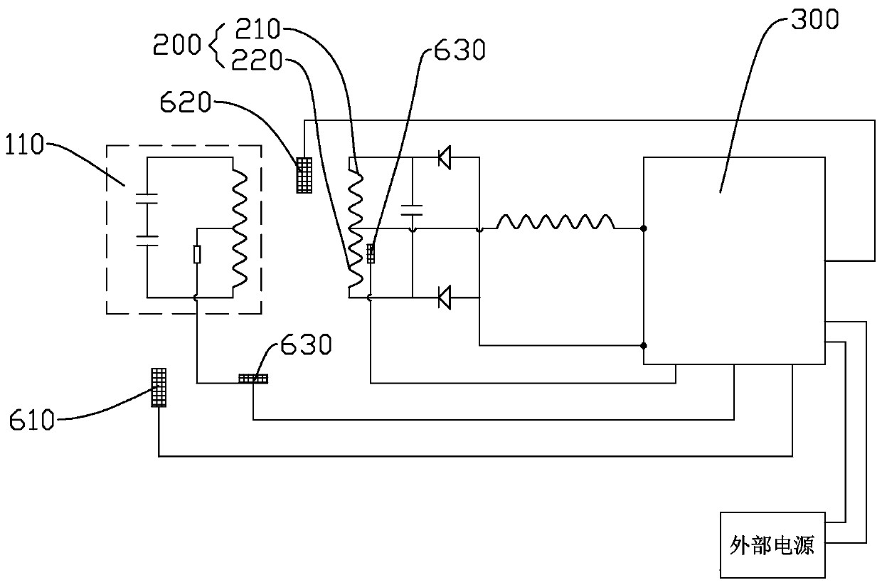
[0029] reference Figure 4 As a preferred embodiment, the AC signal generating unit 300 includes a microprocessor 310, a frequency converter 320, and a power amplifier module 330. The input end of the frequency converter 320 can be electrically connected to an external AC power supply. The microprocessor 310 and the frequency converter 320 The control terminal of the inverter 320 is electrically connected to the input terminal of the power amplifier module 330, the second output terminal of the inverter 320 is electrically connected to the ultrasonic transducer 400, and the power amplifier module 330 The output terminal is connected to the excitation coil 200.
[0030] Under the control of the microprocessor 310, the inverter 320 converts the mains power into a higher frequency AC signal. Because the excitation coil 200 uses electromagnetic induction to make the metal heating element 110 require a large amount of power to heat the water flow, in order to make the excitation coil 200 can have enough power to make the metal heating element 110 quickly heat the water flow. The frequency converter 320 outputs the AC signal to the power amplifier module 330, and transmits the AC signal to the excitation coil 200 after increasing the power of the AC signal. In addition, the frequency converter 320 outputs an AC signal to the ultrasonic transducer 400, and the ultrasonic transducer 400 converts the AC signal into ultrasonic vibration, thereby causing the water pipe 100 to vibrate to achieve the effect of removing scale.
[0031] According to the principle of electromagnetic induction, the greater the rate of change of the magnetic field generated by the excitation coil 200, the greater the eddy current generated by the metal heating element 110, and thus the greater the heat generation of the metal heating element 110. Therefore, the microcontroller can control the inverter 320 The frequency of the output AC signal to achieve the effect of controlling the temperature of the outlet water. The microprocessor 310 may be a device capable of receiving, processing, and outputting signals, such as a single-chip microcomputer or an embedded chip. The power amplifying module 330 may be a common power amplifying circuit mainly composed of IGBTs, or a power amplifying circuit mainly composed of triodes.
[0032] reference figure 1 with Figure 4 As a preferred embodiment, it further includes a control panel 500, which is electrically connected to the microprocessor 310. The user can set parameters such as the outlet water temperature through the control panel 500, and the microprocessor 310 controls the inverter 320 to output an AC signal of appropriate frequency according to the set outlet temperature value, so that the outlet water temperature conforms to the set value. Convenience. The control panel 500 is preferably provided with an operating element 510 and a display screen 520, and the operating element 510 and the display screen 520 are electrically connected to the microprocessor 310. The manipulation element 510 may be a device capable of generating electrical signals according to manipulation actions, such as a knob or a button.
[0033] reference image 3 with Figure 4 In order to stabilize the temperature of the outlet water of the water pipe 100, as a preferred embodiment, an outlet temperature sensor 610 is further included. The microprocessor 310 is electrically connected to the outlet temperature sensor 610, and the outlet temperature sensor 610 is located at the outlet 101 of the water pipe 100.
[0034] The outlet water temperature sensor 610 detects the temperature of the water flow at the outlet 101 of the water pipe 100, and transmits the detected outlet water temperature value signal to the microprocessor 310. The microprocessor 310 adjusts the frequency of the AC signal output by the inverter 320 according to the temperature value signal, Furthermore, the stability of the outlet water temperature can be maintained, so as to prevent the outlet water temperature from being too high or too low, avoid troublesome use, and improve the use experience. In some embodiments, the microprocessor 310 can display the temperature of the water through the display screen 510.
[0035] reference image 3 with Figure 4 As a preferred embodiment, it also includes an inlet water temperature sensor 620 and a working temperature sensor 630. The microprocessor 310 is electrically connected to the inlet water temperature sensor 620 and the working temperature sensor 630, respectively. The inlet water temperature sensor 620 is located at the inlet of the water pipe 100. At the nozzle 102, the working temperature sensor 630 is located on the excitation coil 200 or the metal heating element 110.
[0036] By detecting the water inlet temperature value at the water inlet 102 of the water pipe 100 by the inlet water temperature sensor 620, the temperature information of the water flow in the water pipe 100 can be obtained more comprehensively, and the microprocessor 310 can be combined with the inlet water according to the set outlet temperature value. The temperature value control inverter 320 outputs an AC signal of a suitable frequency to make the outlet water temperature close to the set outlet water temperature.
[0037] The working temperature sensor 630 obtains the temperature value of the excitation coil 200 or the metal heating element 110 during operation and transmits it to the microprocessor 310. When the temperature of the excitation coil 200 or the metal heating element 110 is too high, that is, a malfunction occurs, the microprocessor 310 The inverter 320 can be controlled to stop working in time to prevent accidents and improve safety and reliability. Preferably, there are two working temperature sensors 630, and the two working temperature sensors 630 respectively detect the temperature of the excitation coil 200 and the metal heating element 110.
[0038] reference figure 2 In order to improve the heating efficiency, as a preferred embodiment, a heat insulation layer 120 is provided on the water pipe 100, and the excitation coil 200 is wound outside the heat insulation layer 120.
[0039] Since the metal heating element 110 is located in the heat insulation layer 120, it can prevent the heat generated by the metal heating element 110 from being dissipated under the action of electromagnetic induction, which is beneficial to make the heat generated by the metal heating element 110 more conductive to the water flow, and improve energy utilization rate. The heat insulation layer 120 may be formed of materials such as polyurethane foam or asbestos.
[0040] reference figure 1 with figure 2 As a preferred embodiment of the thermal insulation layer 120, the thermal insulation layer 120 includes a glass tube 121 and a glass fiber layer 122 disposed outside the glass tube 121.
[0041] The glass tube 121 has good heat resistance and is suitable for working with the metal heating element 110, and the glass tube 121 has excellent corrosion resistance, will not affect the water quality, and has a long service life. At the same time, the glass tube 121 has high strength and can handle Pressure from inside and outside improves the stability of the structure. In addition, a glass fiber layer 122 is provided outside the glass tube 121, which can further improve the thermal insulation performance, which is beneficial to further improve the heating efficiency.
[0042] In some embodiments, the water pipe 100 may be made of glass material, and the heat insulation layer 120 may only include the glass fiber layer 122 in this case.
[0043] As a preferred embodiment, the surface of the metal heating element 110 is provided with a negative ion temperature-sensitive coating layer. When the negative ion temperature-sensitive coating layer is heated by the metal heating element 110, it can generate negative ions to be emitted into the water stream, so that the water stream carries negative ions, which is beneficial to sterilizing the water stream. The negative ion temperature-sensitive coating layer can be made of a coating formed of titanium and gadolinium powder.
[0044] In some embodiments, the metal heating element 110 may be provided with an insulating layer on the surface, and a negative ion temperature-sensitive coating layer is arranged outside the insulating layer. Although the metal heating element 110 generates an eddy current under electromagnetic induction, the voltage is not very high. There is no danger to the user, but the metal heating element 110 is isolated from the water flow by the insulating layer, so as to prevent the metal heating element 110 from contacting the water flow, which can further improve safety. The insulating layer can be a polyimide film, which has good heat resistance and thermal conductivity.
[0045] reference Figure 1 to Figure 3 As a preferred embodiment, the excitation coil 200 includes a first coil 210 and a second coil 220. The first coil 210 and the second coil 220 are interleaved on the water pipe 100, and the winding direction of the first coil 210 is the same as that of the second coil. The winding direction of 220 is the same. One end of the first coil 210 and one end of the second coil 220 are connected to form a common end. The other end of the first coil 210, the other end of the second coil 220, and the common end are electrically connected to the AC signal generating unit 300. connection.
[0046] The first coil 210 and the second coil 220 are interleaved, that is, the double-wire winding method is adopted. When the same number of turns is wound, the total number of turns of the double-wire winding is that only one wire is used for winding Since the magnetic field intensity generated by the excitation coil 200 is related to the total number of turns, the double-wire winding method is beneficial to enhance the magnetic field intensity and is convenient for winding.
[0047] As a preferred embodiment, the frequency range of the signal generated by the AC signal generating unit 300 is from 140 KHz to 1.5 MHz, which is beneficial to allow the metal heating element 110 to generate suitable heat generation, and is beneficial to stimulate the negative ion temperature-sensitive coating.
[0048] The above-mentioned embodiments are only preferred solutions of the present invention, and the present invention can also have other embodiments. Those skilled in the art can make equivalent modifications or substitutions without departing from the spirit of the present invention, and these equivalent modifications or substitutions are all included in the scope set by the claims of this application.

PUM

no PUM

Description & Claims & Application Information

We can also present the details of the Description, Claims and Application information to help users get a comprehensive understanding of the technical details of the patent, such as background art, summary of invention, brief description of drawings, description of embodiments, and other original content. On the other hand, users can also determine the specific scope of protection of the technology through the list of claims; as well as understand the changes in the life cycle of the technology with the presentation of the patent timeline. Login to view more.

Similar technology patents

Grain threshing machine with stable running

InactiveCN105359734AFast threshing speedAvoid savingThreshersPush outEngineering
Owner:GUILIN UNIV OF AEROSPACE TECH

Drug virtual screening method

InactiveCN108256284AImprove convenienceAvoid savingMolecular designChemical structure searchDrugDatabase server
Owner:SUN YAT SEN UNIV

Classification and recommendation of technical efficacy words

  • Heating fast
  • Avoid saving

Grain threshing machine with stable running

InactiveCN105359734AFast threshing speedAvoid savingThreshersPush outEngineering
Owner:GUILIN UNIV OF AEROSPACE TECH

Drug virtual screening method

InactiveCN108256284AImprove convenienceAvoid savingMolecular designChemical structure searchDrugDatabase server
Owner:SUN YAT SEN UNIV
Why Eureka
Try Eureka