
Reelable optical fiber ribbon and method of manufacturing same

A manufacturing method and technology for optical fiber ribbons, applied in the directions of light guides, optics, optical components, etc., can solve the problems of poor winding function of optical fiber ribbons, slow point-shaped glue supply, etc., and achieve the effect of good flexibility and improved optical transmission performance.

Active Publication Date: 2020-04-10
NANJING WASIN FUJIKURA OPTICAL COMM LTD
View PDF7 Cites 5 Cited by
  • Summary
  • Abstract
  • Description
  • Claims
  • Application Information

AI Technical Summary

Problems solved by technology

[0002] Windable optical fiber ribbon is a new type of optical fiber ribbon that can realize large core count and miniaturization of optical cable. According to the existing literature and patent retrieval results, it is roughly a kind of optical fiber ribbon made by Corning Corporation of the United States. The tape winding function is relatively poor, and there is also a mesh optical fiber ribbon, which has a better winding function, but because the point-shaped glue supply speed is relatively slow, the present invention provides a new type of optical fiber ribbon structure, which can improve the rollability of the optical fiber ribbon. The winding function can also increase the production speed substantially, and can also improve the PMD performance of the optical fiber ribbon

Method used


Image

  • Reelable optical fiber ribbon and method of manufacturing same
  • Reelable optical fiber ribbon and method of manufacturing same
  • Reelable optical fiber ribbon and method of manufacturing same

Examples


Embodiment Construction

[0026] In order to make the object, technical solution and advantages of the present invention clearer, the present invention will be further described in detail below in combination with specific embodiments and with reference to the accompanying drawings. It should be understood that these descriptions are exemplary only, and are not intended to limit the scope of the present invention. Also, in the following description, descriptions of well-known structures and techniques are omitted to avoid unnecessarily obscuring the concept of the present invention.

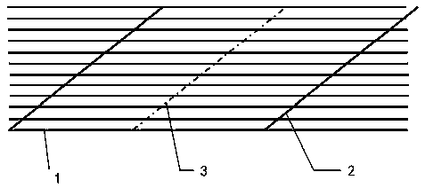
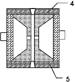
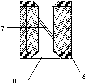
[0027] Such as Figure 1-4 As shown, the reelable optical fiber ribbon proposed by the present invention includes an optical fiber ribbon main body 1 , the front of the optical fiber ribbon main body is sprayed with a front optical fiber ribbon resin 2 , and the back of the optical fiber ribbon main body is sprayed with a back optical fiber ribbon resin 3 .

[0028] In this embodiment, it should be noted that the front o...


PUM

PropertyMeasurementUnit
widthaaaaaaaaaa

Abstract

The invention belongs to the technical field of reelable optical fiber ribbons, and particularly relates to a reelable optical fiber ribbon and a manufacturing method thereof. The reelable optical fiber ribbon comprises an optical fiber ribbon main body, wherein the front face of the optical fiber ribbon main body is sprayed with front-face optical fiber ribbon resin, and the back face of the optical fiber ribbon main body is sprayed with back-face optical fiber ribbon resin. The manufacturing method comprises the manufacturing steps of: S1, preparing an eye mold, wherein the eye mold comprises a mold body, an upper cover plate is fixed to the upper end face of the mold body, a lower cover plate is fixed to the lower end face of the mold body, and glue supply holes matched with front-faceoptical fiber ribbon resin and back-face optical fiber ribbon resin in position and size are formed in the two sides of the mold body respectively; S2, putting the optical fiber ribbon main body froman optical fiber inlet of the eye mold, introducing optical fiber ribbon resin by means of the glue supply holes, pulling the optical fiber ribbon main body, and introducing the optical fiber ribbon resin; the flatness of the optical fiber ribbon is guaranteed by means of front face and back face gluing, the optical fiber ribbon is guaranteed not prone to loose completely after being stressed to the maximum extent, the front and back faces are not glued at the same time, and the optical fiber ribbon is guaranteed to be better in flexibility.

Description

technical field [0001] The invention relates to the technical field of winding optical fiber ribbons, in particular to winding optical fiber ribbons and a manufacturing method thereof. Background technique [0002] Windable optical fiber ribbon is a new type of optical fiber ribbon that can realize large core count and miniaturization of optical cable. According to the existing literature and patent retrieval results, it is roughly a kind of optical fiber ribbon made by Corning Corporation of the United States. The tape winding function is relatively poor, and there is also a mesh optical fiber ribbon, which has a better winding function, but because the point-shaped glue supply speed is relatively slow, the present invention provides a new type of optical fiber ribbon structure, which can improve the rollability of the optical fiber ribbon. The winding function can also increase the production speed substantially, and at the same time, it can also improve the PMD performanc...

Claims


Application Information

Patent Timeline
Patent Type & Authority Applications(China)
IPC IPC(8): G02B6/44
CPCG02B6/4403G02B6/4429G02B6/448
Inventor 张成龙李起龙王小泉杜海涛
Owner NANJING WASIN FUJIKURA OPTICAL COMM LTD
Learn More