
Small magnetic ring inductor winding device

A magnetic ring inductance and winding device technology, which is applied in coil manufacturing and other directions, can solve the problems of high cost, unfavorable promotion and use, and inconvenient use of small magnetic rings, and achieve the effects of avoiding waste, rational use, and enhancing stackability

Active Publication Date: 2020-04-10
岳明洋
View PDF6 Cites 0 Cited by
  • Summary
  • Abstract
  • Description
  • Claims
  • Application Information

AI Technical Summary

Problems solved by technology

[0003] Aiming at the deficiencies of the prior art, the present invention provides a small magnetic ring inductance winding device, which solves the current trend of shrinking the structure size of electronic products, resulting in a reduction in the size of the inductance, because the cost of the inductance is relatively low , so most of the inductors are wound by machines, but there are small magnetic ring inductors on the market at present. The rewinding process of such small magnetic ring inductors is only 1.5-2mm in diameter, so there is currently no way to effectively mass produce them. They are all made by manual winding by workers, which leads to an increase in the cost of using the small magnetic ring, so the current magnetic winding device is inconvenient to use, which is not conducive to the promotion and use of the problem

Method used


Image

  • Small magnetic ring inductor winding device
  • Small magnetic ring inductor winding device
  • Small magnetic ring inductor winding device

Examples


Embodiment Construction

[0033] The following will clearly and completely describe the technical solutions in the embodiments of the present invention with reference to the accompanying drawings in the embodiments of the present invention. Obviously, the described embodiments are only some, not all, embodiments of the present invention. Based on the embodiments of the present invention, all other embodiments obtained by persons of ordinary skill in the art without making creative efforts belong to the protection scope of the present invention.

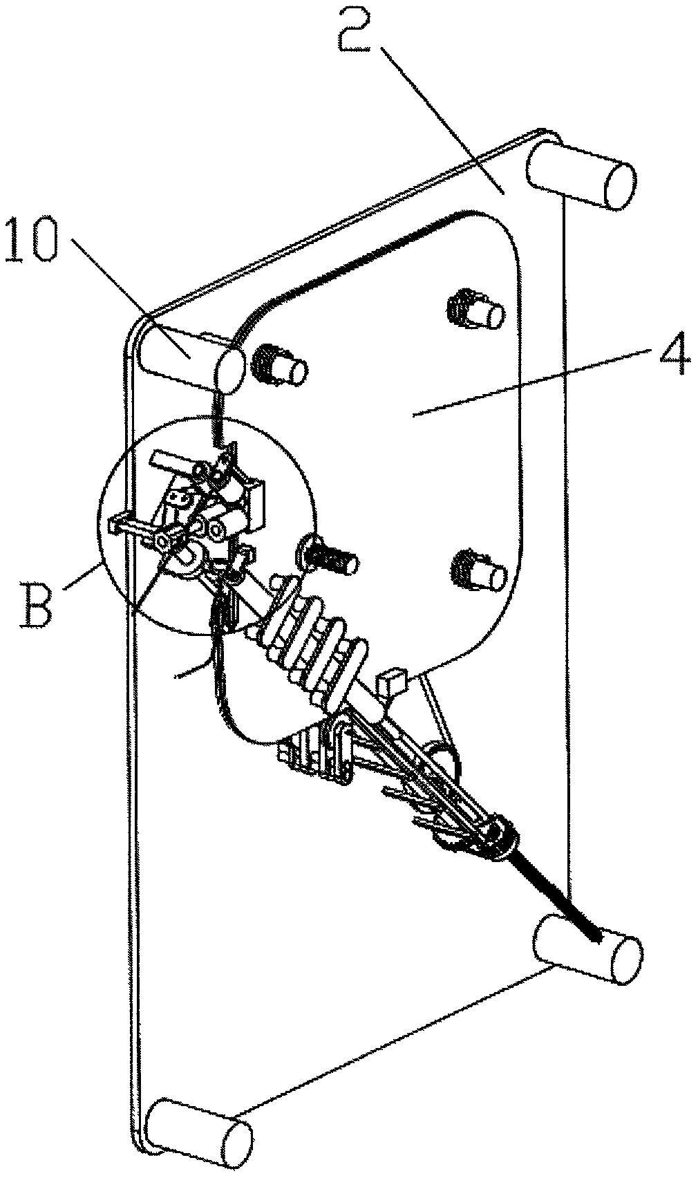
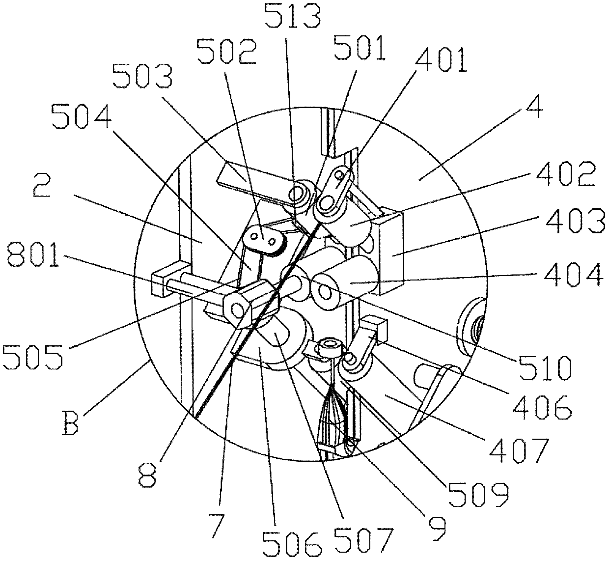
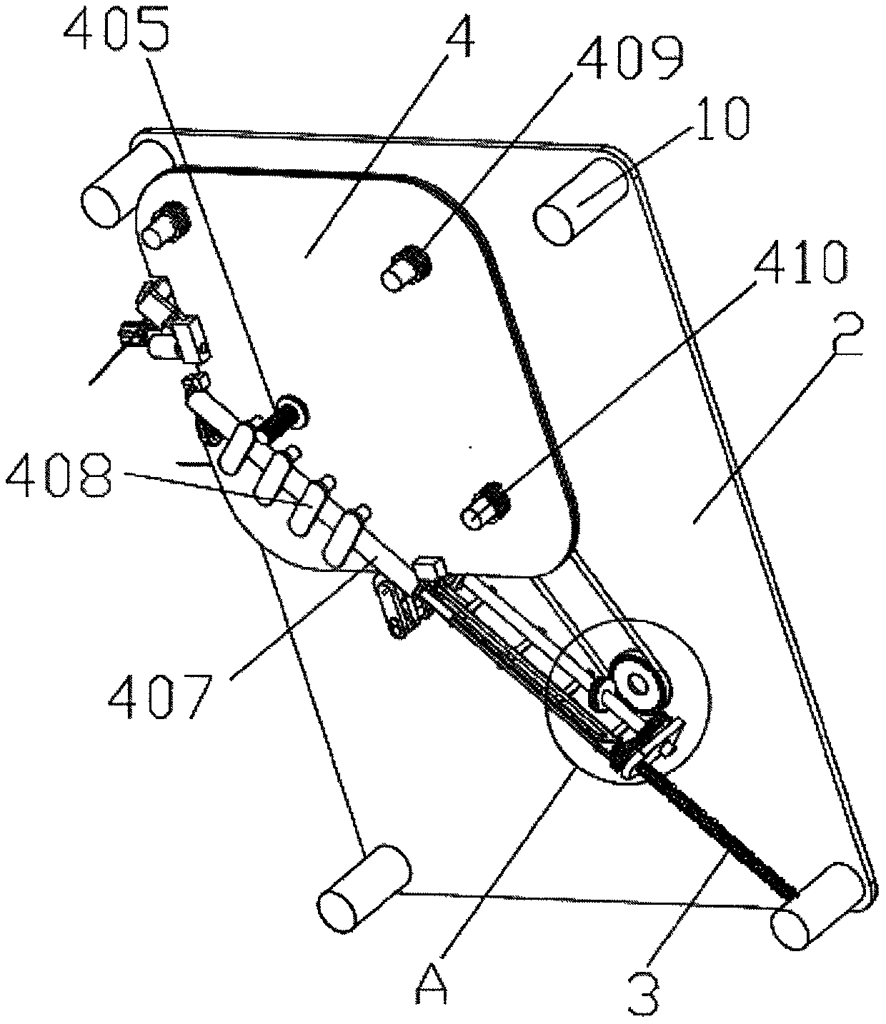
[0034] see figure 1 , figure 2 , image 3 , Figure 4 , Figure 5 , Figure 6 , Figure 7 , Figure 8 , Figure 9 , Figure 10 , Figure 11 , Figure 12 , Figure 13 , Figure 14 , Figure 15 , Figure 16 , Figure 17 , Figure 18 As shown, the present invention provides a technical solution: a small magnetic ring inductance winding device, including a left panel 1, a right panel 2, a left limiting plate 4 and a right limiting plate 5, the fro...


PUM


Abstract

The invention relates to the technical field of mechanical devices, and discloses a small magnetic ring inductor winding device. The small magnetic ring inductor winding device comprises a left panel,a right panel, a left limiting plate and a right limiting plate, and the front face of the right panel is fixedly connected with a right limiting sheet driving wheel support, a top end transmission movable shaft support, a right end enameled wire middle feeding shaft support, a middle transmission shaft support and a tail end transmission shaft support in sequence from left upper portion to rightlower portion. A modular design is adopted, side-by-side installation can be realized as required during batch production, a long-end limiting sheet and a short-end limiting sheet with variable lengths are arranged, the advancing track of the head of the varnished wire is limited, and then an enameled wire is used reasonably; and through the eccentric connection mode of the top end of the guide cover and the positioning ring, when the end of the enameled wire after the first circle passes through the small magnetic ring, the enameled wire can be arranged in sequence along the gap between thepositioning ring and the small magnetic ring, so that the phenomenon of frame erection between two adjacent circles is prevented.

Description

technical field [0001] The invention relates to the technical field of mechanical devices, in particular to a small magnetic ring inductance winding device. Background technique [0002] An inductor is a component that can convert electrical energy into magnetic energy and store it. The structure of an inductor is similar to a transformer, but there is only one winding. The inductor has a certain inductance, which only hinders the change of current. In the state, when the circuit is turned on, it will try to prevent the current from flowing through it; if the inductor is in the state of current passing, it will try to maintain the current when the circuit is disconnected. Inductors are also called chokes, reactors, Dynamic reactor, now with the trend of shrinking the structure size of electronic products, the size of the inductor is also reduced. Because the cost of the inductor is relatively low, most of the inductors are wound by machines, but there are small ones on the m...

Claims


Application Information

Patent Timeline
Patent Type & Authority Applications(China)
IPC IPC(8): H01F41/06H01F41/08
CPCH01F41/06H01F41/08
Inventor 岳明洋
Owner 岳明洋
Learn More