Signal receiving angle control device and control method thereof

A technology for signal reception and control devices, applied in antennas, electrical components, etc., can solve problems such as poor customer experience and reduced communication quality, achieve a good user experience, and avoid the effect of reducing communication quality

Active Publication Date: 2022-03-25
VIVO MOBILE COMM CO LTD
View PDF9 Cites 0 Cited by
  • Summary
  • Abstract
  • Description
  • Claims
  • Application Information

AI Technical Summary

Problems solved by technology

[0006] The invention discloses a control device for a signal receiving angle, electronic equipment and a control method for a signal receiving angle, so as to solve the problem that the communication quality of the existing electronic equipment is reduced during use, resulting in poor customer experience

Method used


Image

  • Signal receiving angle control device and control method thereof
  • Signal receiving angle control device and control method thereof

Examples


Embodiment Construction

[0021] In order to make the purpose, technical solution and advantages of the present invention clearer, the technical solution of the present invention will be clearly and completely described below in conjunction with specific embodiments of the present invention and corresponding drawings. Apparently, the described embodiments are only some of the embodiments of the present invention, but not all of them. Based on the embodiments of the present invention, all other embodiments obtained by persons of ordinary skill in the art without making creative efforts belong to the protection scope of the present invention.

[0022] The technical solutions disclosed by various embodiments of the present invention will be described in detail below in conjunction with the accompanying drawings.

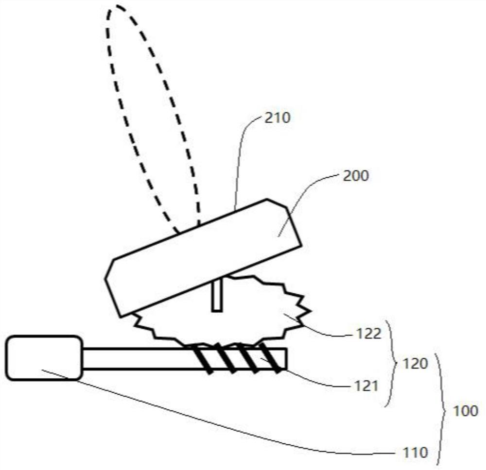
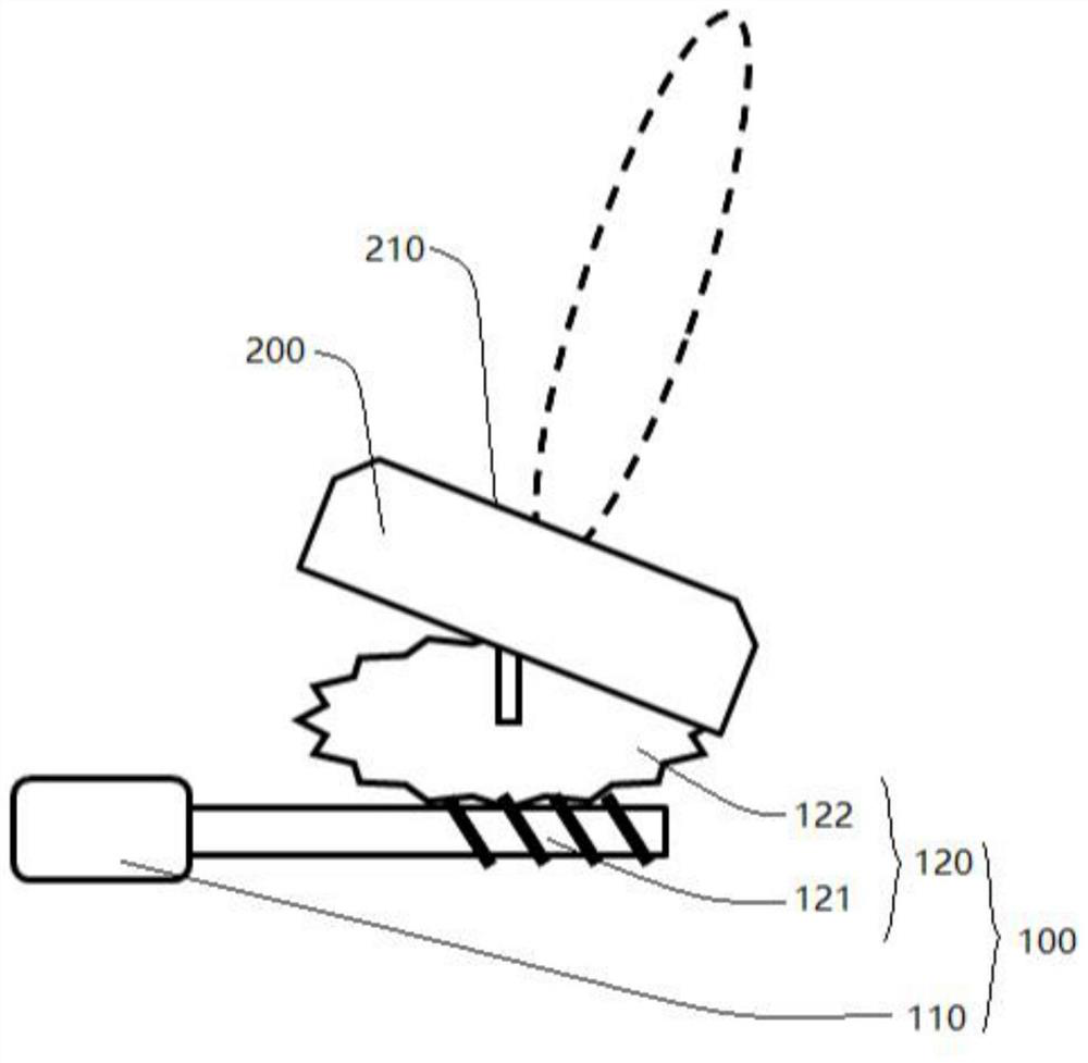
[0023] Please refer to figure 1 and figure 2 , the embodiment of the present invention discloses a signal receiving angle control device, which includes a driving device 100 and a signal tran...


PUM


Abstract

The invention discloses a control device for a signal receiving angle, which includes a driving device and a signal transceiving device, the driving device drives the signal transceiving device to rotate, the signal transceiving device has a signal processing surface, and the signal processing surface is arranged obliquely or parallel to the rotating shaft of the signal transceiving device set up. The signal receiving angle control device disclosed in the present invention uses the signal processing surface on the signal transceiver device to receive the signal of the antenna. When the user adjusts the direction at high frequency and irregularly, the driving device will drive the signal transceiver device to rotate so that the signal The orientation of the processing surface changes to ensure that the signal processing surface can receive enough antenna signals, thereby avoiding communication quality degradation and ensuring a good user experience. The invention also discloses an electronic device and a control method for the signal receiving angle.

Description

technical field [0001] The invention relates to the technical field of communication equipment, in particular to a control device for a signal receiving angle, electronic equipment and a control method for a signal receiving angle. Background technique [0002] Enhanced mobile broadband (eMBB) application scenarios are mainly for electronic devices such as mobile phones, tablet computers, data cards, etc.; 5G mobile phone terminals need to meet the key technical characteristics of eMBB scenarios, including high data rate, high traffic density, and high-speed mobile Adaptability; low-power massive connection (massive machine type communication, mMTC) scenarios, mainly for massive IoT communications; low-latency and high-reliability (ultrareliable low latency, uRLLC) application scenarios, mainly for telemedicine and V2X such as Internet of Vehicles, applications such as autonomous driving. [0003] For the design of 5G antennas, especially the antennas in the frequency band ...

Claims


Application Information

Patent Timeline
Patent Type & Authority Patents(China)
IPC IPC(8): H01Q3/08
CPCH01Q3/08
Inventor 张巧逢
Owner VIVO MOBILE COMM CO LTD
Why Eureka
Try Eureka