Flow-collecting universal rotary joint structure for multi-channel electric signal transmission

A rotary joint, multi-channel signal technology, applied in the direction of flexible/rotatable wire connectors, circuits, connections, etc., can solve problems affecting electrical signal transmission, breakage, wire winding, etc., to ensure cleanliness, reduce rotational torque, Easy and simple to install

Active Publication Date: 2020-04-10
SHAANXI BAOCHENG AVIATION INSTR
View PDF8 Cites 0 Cited by
  • Summary
  • Abstract
  • Description
  • Claims
  • Application Information

AI Technical Summary

Problems solved by technology

[0002] In the wire transmission, the universal rotary joint is mainly used in conjunction with the sling, which can effectively avoid the sling knotting. With the advancement of technology, some hanging systems need to transmit multiple electrical signals with the sling, and directly use wires to transmit electrical signals , but during use, due to the rotation of the suspended object, it is easy to cause the wires to be entangled or broken, which will affect the transmission of electrical signals. In order to ensure the quality of signal transmission and avoid wire breakage, it is necessary to improve

Method used


Image

  • Flow-collecting universal rotary joint structure for multi-channel electric signal transmission
  • Flow-collecting universal rotary joint structure for multi-channel electric signal transmission
  • Flow-collecting universal rotary joint structure for multi-channel electric signal transmission

Examples


Embodiment Construction

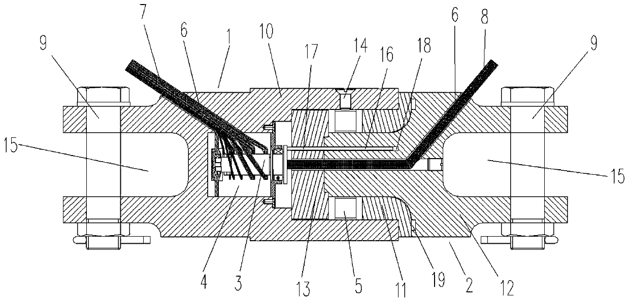
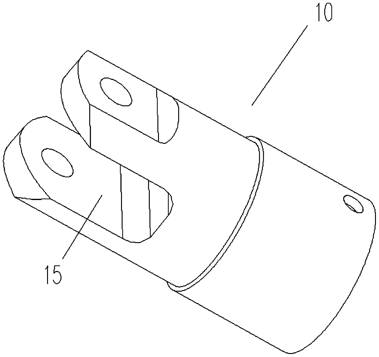
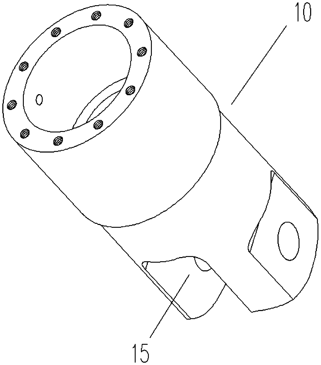
[0020] Attached below Figure 1-5 An embodiment of the present invention is described so as to clearly and completely describe the technical solution. Obviously, the described embodiment is only a part of the embodiments of the present invention, rather than all the embodiments.

[0021] In describing the present invention, it should be understood that the terms "upper", "lower", "front", "rear", "left", "right", "top", "bottom", "inner", " The orientation or positional relationship indicated by "outside", etc. is based on the orientation or positional relationship shown in the drawings, which is only for the convenience of describing the present invention and simplifying the description, rather than indicating or implying that the referred device or element must have a specific orientation, so as to Specific orientation configurations and operations, therefore, are not to be construed as limitations of the invention.

[0022] A current-collecting universal rotary joint struc...


PUM


Abstract

The utility model provides a flow-collecting universal rotary joint structure for multi-channel electric signal transmission. Lead holes are formed in an upper rotating body assembly and a lower rotating body assembly; a conductive slip ring is mounted in the inner cavity of the upper rotating body assembly; a plurality of paths of signal leading-out wires I at the left end of the conductive slipring are led out from the lead hole in the upper rotating body assembly; the left end of the lower rotating body assembly is inserted into the inner cavity and connected with the right end of the conductive slip ring; a plurality of signal outgoing lines II at the right end of the conductive slip ring are led out from the lead hole in the lower rotating body assembly, the lower rotating body assembly is rotationally connected with the upper rotating body assembly through a bearing arranged in the inner cavity, and the left end of the upper rotating body assembly and the right end of the lowerrotating body assembly are connected with slings on the corresponding sides through plug pins. The flow-collecting universal rotary joint structure can freely rotate by 360 degrees, the phenomenon that wires are intertwined or broken under the condition that a hung object frequently rotates is avoided, the sling is effectively prevented from being knotted, installation is convenient and easy, thebearing capacity is high, the weight is light, reliability is high, and electric signals do not interfere with one another, are not attenuated and are not distorted in the rotating process.

Description

technical field [0001] The invention belongs to the technical field of cable joints, and in particular relates to a current-collecting universal rotary joint structure capable of transmitting multiple electrical signals. Background technique [0002] In the wire transmission, the universal rotary joint is mainly used in conjunction with the sling, which can effectively avoid the sling knotting. With the advancement of technology, some suspension systems need to transmit multiple electrical signals with the sling, and directly use the wire to transmit the electrical signal , but during use, due to the rotation of the suspended object, it is easy to cause the wires to be entangled or broken, which affects the transmission of electrical signals. In order to ensure the quality of signal transmission and avoid wire breakage, it is necessary to improve. Contents of the invention [0003] The technical problem solved by the present invention is to provide a current-collecting uni...

Claims


Application Information

Patent Timeline
IPC IPC(8): H01R35/04
CPCH01R35/04
Inventor 雒晓科陈康付丙申
Owner SHAANXI BAOCHENG AVIATION INSTR
Why Eureka
Try Eureka