WIRELESS CHARGING electronic device and method

A technology of electronic equipment and wireless charging, which is applied in the direction of secondary battery charging/discharging, conversion equipment without intermediate conversion to AC, battery circuit devices, etc., can solve the actual needs of electronic equipment that is difficult to be charged, and achieve rich functions, Flexible switching, the effect of improving switching efficiency

Active Publication Date: 2020-04-10
HUAWEI DIGITAL POWER TECH CO LTD
View PDF5 Cites 3 Cited by
  • Summary
  • Abstract
  • Description
  • Claims
  • Application Information

AI Technical Summary

Problems solved by technology

[0004] Existing electronic devices that support reverse charging are difficult to flexibly meet the actual needs of the electronic device being charged when implementing wireless charging

Method used


Image

  • WIRELESS CHARGING electronic device and method
  • WIRELESS CHARGING electronic device and method
  • WIRELESS CHARGING electronic device and method

Examples


Embodiment 1

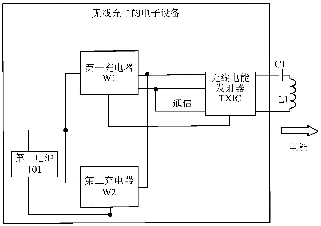
[0117] see figure 2 , which is a schematic structural diagram of a wireless charging electronic device provided in an embodiment of the present application.

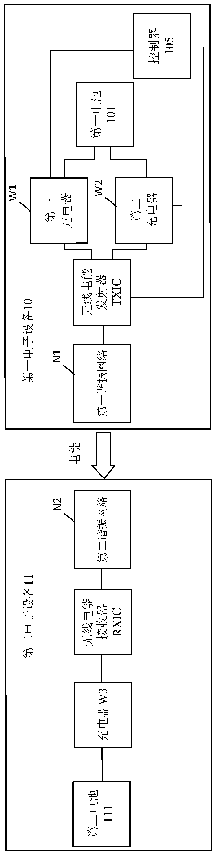
[0118] The electronic device can be used as the first electronic device in figure 1 The implementation scenario of the reverse wireless architecture is shown. The electronic device is used as a reverse charging terminal for wirelessly charging the electronic device to be charged.

[0119] like figure 2 As shown, the wireless charging electronic device provided in this embodiment includes: a first charger W1, a second charger W2, a wireless power transmitter TXIC, a power coil L1, a first battery 111 and a controller. where the controller is not in figure 2 Shows. exist figure 2 In the electronic device shown, the power coil L1 and the first resonant capacitor C1 are co-located in the first resonant network.

[0120] The first charger W1 includes a closed-loop DC-DC converter, and the second charger W2 includes...

Embodiment 2

[0146] see Figure 5 , which is a schematic diagram of reverse wireless charging performed by another wirelessly charged electronic device provided in an embodiment of the present application. Figure 5 and subsequent Figure 7 The charged sub-device contained in the Figure 4 The specific structures of the electronic devices to be charged shown are basically the same, so they will not be described in detail here.

[0147] The electronic device can be used as the first electronic device 10 figure 1 The implementation scenario of the reverse wireless architecture is shown. The electronic device is used as a reverse charging terminal for wirelessly charging the electronic device to be charged.

[0148] like Figure 5 As shown, the wireless charging electronic device provided in this embodiment includes: a first charger W1, a second charger W2, a boost circuit 104, a wireless power transmitter TXIC, a power coil L1, a first battery 101 and a controller. where the controller...


PUM


Abstract

The invention discloses a wireless charging electronic device and method. The electronic device can support charging of other electronic devices. The electronic device comprises a first charger and asecond charger, the first charger comprises a closed-loop DC-DC converter, the second charger comprises an open-loop DC-DC converter. Due to the fact that the first charger adopts the closed-loop DC-DC converter, continuous adjustment of the output voltage can be achieved according to requirements, and therefore the charging stability of charged electronic device can be improved. Due to the fact that the second charger adopts the open-loop DC-DC converter, the energy conversion efficiency of the second charger is high, and therefore the charging efficiency of charged electronic device can be improved. According to the controller of the wireless charging electronic device provided by the invention, one of the first charger and the second charger can be flexibly selected to work according tothe required power of the charged electronic device, so that the advantages of the first charger and the second charger in different charging stages are fully exerted, and it is guaranteed that highstability and high charging efficiency are achieved during charging.

Description

technical field [0001] The present application relates to the technical field of charging, in particular to an electronic device and method for wireless charging. Background technique [0002] Portable electronic devices have been widely used in recent years. The traditional way of charging electronic equipment often requires frequent plugging and unplugging of the power cord, but the device is prone to wear and tear during the plugging and charging process, which has poor safety and also affects the appearance of the electronic equipment. Wireless charging is a new type of energy transmission. Compared with traditional charging methods, wireless charging can solve the above problems well. [0003] At present, many electronic devices can support wireless charging, such as mobile phones, smart watches, Bluetooth headsets, electric toothbrushes, etc. In fact, these electronic devices that can support wireless charging usually only have the forward charging function, that is...

Claims


Application Information

Patent Timeline
Patent Type & Authority Applications(China)
IPC IPC(8): H02J50/12H02J7/00H01M10/44
CPCH02J50/12H01M10/44H02J7/0068H02M3/33571H02M3/01H02J7/02H02J50/10H02J7/04H02M3/07H02M3/156H04B5/0081H04B5/0037Y02E60/10H02M1/007H02J7/00034H02J7/00714H02J7/007182H02J50/80H02J7/0071
Inventor 吴宝善吴东昊蔡兵杨云鹏张成良
Owner HUAWEI DIGITAL POWER TECH CO LTD
Why Eureka
Try Eureka