
A rotary side-drive magnetic motor

An engine, rotary technology, applied in the direction of electromechanical devices, electrical components, etc., can solve problems such as cylinder block damage, engine vibration, engine weakness, etc., to simplify the transmission structure, ensure strong torque, and reduce production requirements.

Active Publication Date: 2021-04-16
重庆恒百力科技有限公司
View PDF2 Cites 0 Cited by
  • Summary
  • Abstract
  • Description
  • Claims
  • Application Information

AI Technical Summary

Problems solved by technology

In order to make the main shaft have enough driving force, the engine is generally designed as a four-stroke structure. The engine needs to provide enough torque to drive the vehicle to walk. The main shaft speed reaches 3000 revolutions per minute. If the speed cannot reach the design speed, the torque of the engine is not enough. Drive the vehicle, but due to the relatively high speed, the vibration of the engine is relatively large, and because of the relatively high sealing requirements, the manufacturing precision is very high. If the gap is slightly smaller, the cylinder block will be damaged due to friction and high temperature. If it is too large, there may be air leakage, causing the engine to be weak, so the requirements for the sealing performance of the engine are relatively strict.

Method used


Image

  • A rotary side-drive magnetic motor
  • A rotary side-drive magnetic motor
  • A rotary side-drive magnetic motor

Examples


Embodiment Construction

[0028] The specific implementation manner of the present invention will be further described below in conjunction with the accompanying drawings.

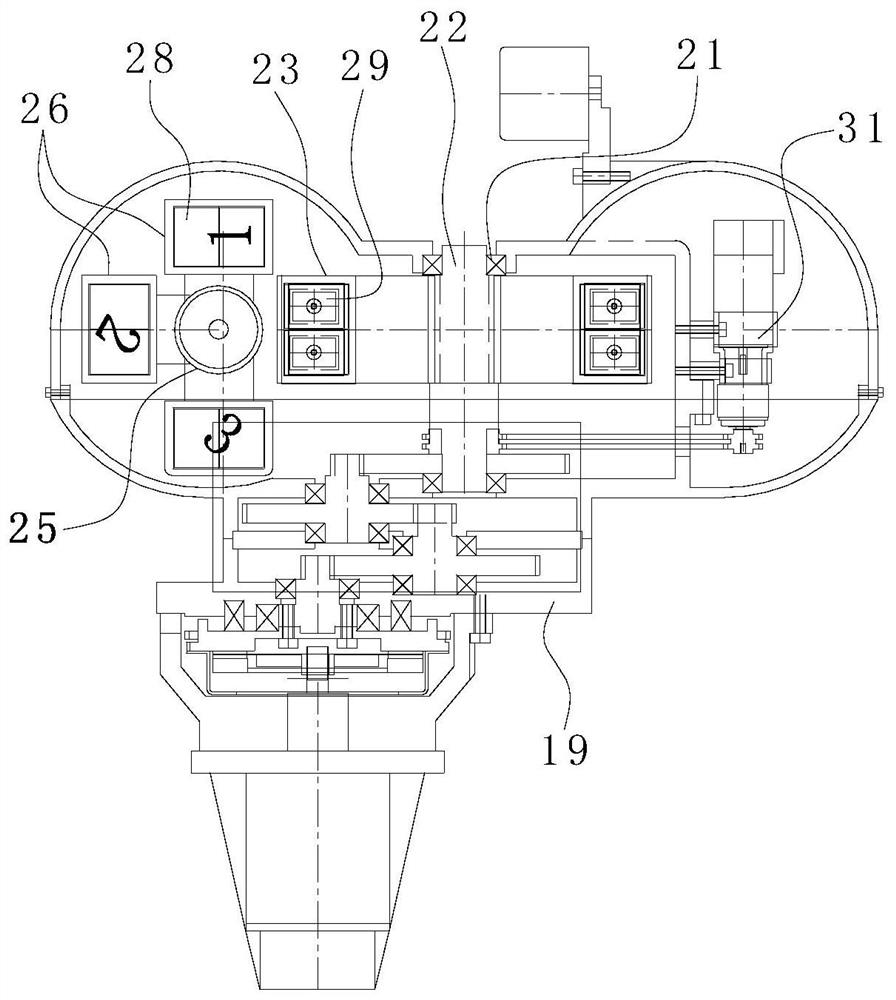
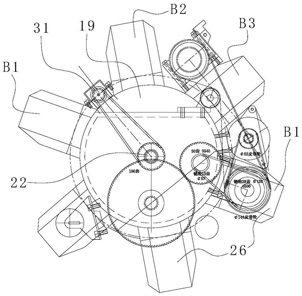
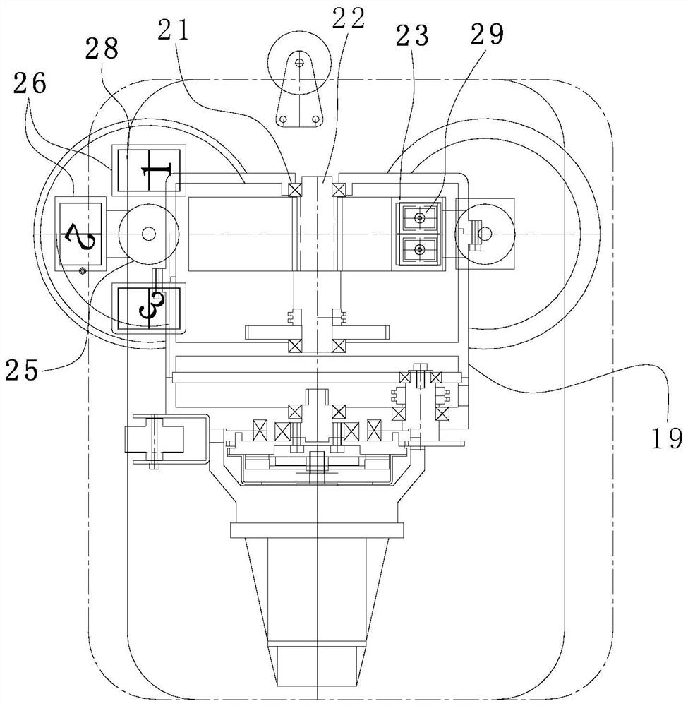
[0029] Such as figure 1 , figure 2 , image 3 , Figure 4 As shown in the figure, a six-wheel drive and four-rotation side-drive magnetic motor of the present invention is shown, which includes a base 19 and a rotating main shaft 22 connected to the base 19 through bearings 21, and four pieces are installed around the base at equal angles The inner magnets 23 on the circumferential side of the rotating main shaft 22, 6 groups of outer magnetic blocks 26 and the driving device for driving the corresponding outer magnetic blocks 26 to rotate along the direction perpendicular to the axis of the drive shaft of the rotating main shaft 22; The magnet block 26 cuts between the two inner magnets 23 in turn and repels each other with the back surface of the front inner magnet 23, the angular position difference between the adjacent inne...


PUM


Abstract

The invention discloses a rotary side-drive magnetic motor, which comprises a base, a rotating main shaft connected to the base through bearings, 2n inner magnets mounted on the circumferential side of the rotating main shaft at equal angles, and 2m sets of outer magnets. The magnetic block and the driving device for driving the corresponding outer magnetic block to rotate along the direction of the axis of the drive shaft perpendicular to the rotating main shaft, m>n≥2; each group of outer magnetic blocks is sequentially cut into between two inner magnets and connected with the front The back and back surfaces of the inner magnets repel each other, the angular position difference between adjacent inner magnets is 360° / (2n), and the running contours of each group of outer magnets form a circular array around the central axis of the rotating spindle. The rotating spindle is driven by the outer magnetic block to the inner magnet. Since the force arm and torque of the edge drive are increased, the torque can be strong, so that the driving force and speed of the outer magnetic block can be reduced, and the car can be driven. Furthermore, the structure of the transmission is simplified, and there is no airtightness requirement for the casing.

Description

technical field [0001] The invention relates to the field of motors, in particular to a rotary side-driven magnetic motor. Background technique [0002] Existing engines have always been driven by ignition and explosion to rotate the crankshaft, and the main shaft transmits the rotational force to the transmission to drive the vehicle to walk as required. In order to make the main shaft have enough driving force, the engine is generally designed as a four-stroke structure. The engine needs to provide enough torque to drive the vehicle to walk. The main shaft speed reaches 3000 revolutions per minute. If the design speed cannot reach the design speed, the torque of the engine is not enough. Drive the vehicle, but due to the relatively high speed, the vibration of the engine is relatively large, and because of the relatively high sealing requirements, the manufacturing precision is very high. If the gap is slightly smaller, the cylinder block will be damaged due to friction an...

Claims


Application Information

Patent Timeline
Patent Type & Authority Patents(China)
IPC IPC(8): H02K53/00
CPCH02K53/00
Inventor 吴建洪罗治斌朱瑞震
Owner 重庆恒百力科技有限公司
Learn More