Grabbing and conveying device for wafer biscuit slice cooling machine
A conveying device and cooling machine technology, applied in the direction of conveyor, conveyor objects, transportation and packaging, etc., can solve the problems of manual placement, chipping, trouble, etc., to reduce the generation of chipping, and achieve uniform adsorption. Effect
- Summary
- Abstract
- Description
- Claims
- Application Information
AI Technical Summary
Problems solved by technology
Method used
Image

Examples
Embodiment Construction
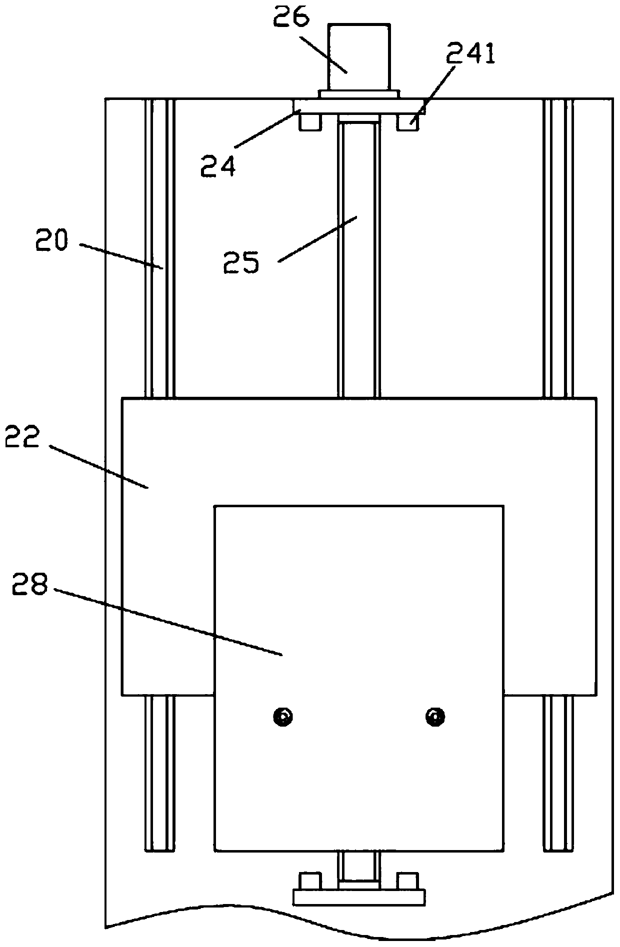
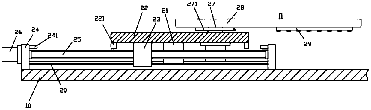
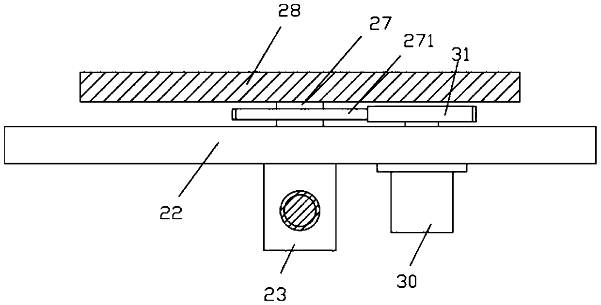
[0015] Examples, see e.g. figure 1 and image 3 Shown, a kind of wafer biscuit slice cooling machine is used grab conveying device, comprises frame 10, and the middle top surface of the top plate of described frame 10 is fixed with upper supporting frame 11, and the rear top of the top plate of frame 10 The left and right sides of the surface are fixed with track bars 20, two track sliders 21 are installed on the track bars 20, the horizontal plate 22 is fixed on the top surface of the two track sliders 21, and the middle part of the bottom surface of the horizontal plate 22 is fixed with a movable Block 23, the middle part and the rear part of the top surface of the top plate of the frame 10 are all fixed with connecting plates 24, and the two ends of the moving screw 25 are hinged on the two connecting plates 24 by bearings, and the rear wall of the connecting plates 24 at the rear The main moving motor 26 is fixed, the output shaft of the main moving motor 26 is a spline s...
PUM
 Abstract
Description
Claims
Application Information
PatSnap Eureka turns technology decisions into work you can execute. Powered by our Innovation Knowledge Graph, it runs expert workflows across engineering, life sciences, materials and intellectual property. Get your review-ready output in minutes.


