Automatic cable feeding device

A wire feeding device and cable technology, applied in the field of cables, can solve the problems of complex structure of the wire feeding device, low production efficiency, and inability to transport cables of various sizes, etc.

Inactive Publication Date: 2020-04-14
浙江龙鹰光电科技有限公司
View PDF0 Cites 3 Cited by
  • Summary
  • Abstract
  • Description
  • Claims
  • Application Information

AI Technical Summary

Problems solved by technology

[0003] At present, the wire ends commonly used in the field of electric power engineering often have to be stripped, and then pressed onto a metal joint for convenient connection between the wire and the electrical appliance. During the peeling process, the cable needs to be transported, but the existing The wire transmission device cannot transport cables of various sizes, resulting in the need for the factory to purchase multiple wire transmission equipment, which increases production costs, and the existing wire transmission device has a complex structure and low production efficiency

Method used


Image

  • Automatic cable feeding device
  • Automatic cable feeding device
  • Automatic cable feeding device

Examples


Embodiment Construction

[0019] The following will clearly and completely describe the technical solutions in the embodiments of the present invention with reference to the accompanying drawings in the embodiments of the present invention. Obviously, the described embodiments are only some, not all, embodiments of the present invention.

[0020] In describing the present invention, it should be understood that the terms "upper", "lower", "front", "rear", "left", "right", "top", "bottom", "inner", " The orientation or positional relationship indicated by "outside", etc. is based on the orientation or positional relationship shown in the drawings, and is only for the convenience of describing the present invention and simplifying the description, rather than indicating or implying that the referred device or element must have a specific orientation, so as to Specific orientation configurations and operations, therefore, are not to be construed as limitations on the invention.

[0021] refer to Figure ...


PUM


Abstract

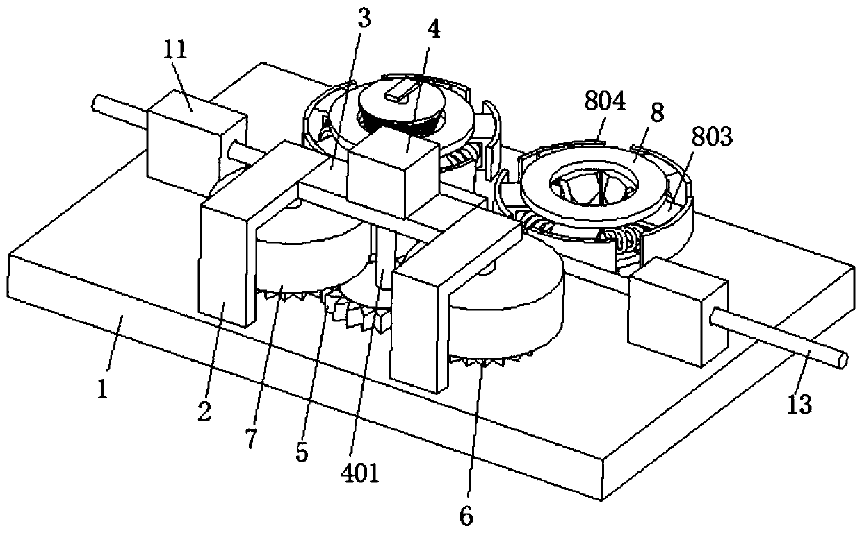
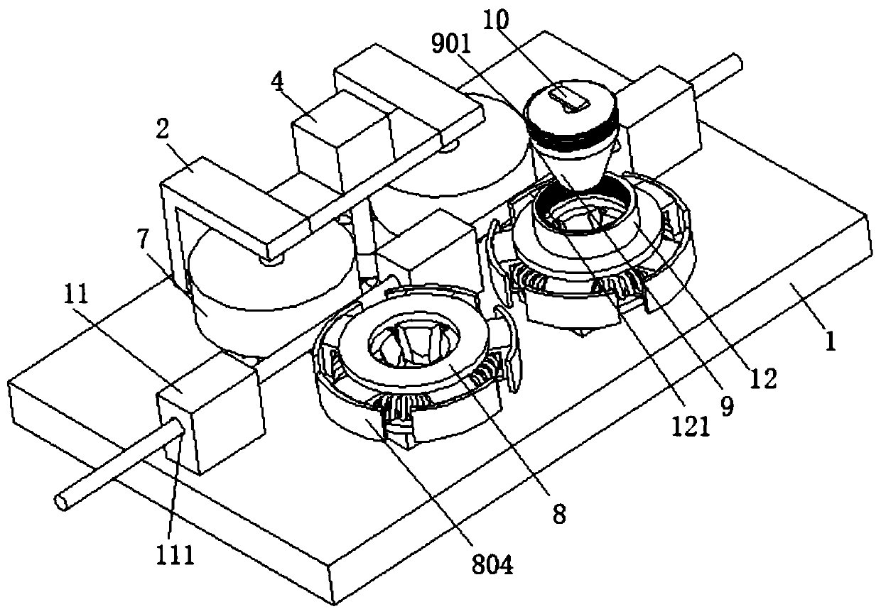
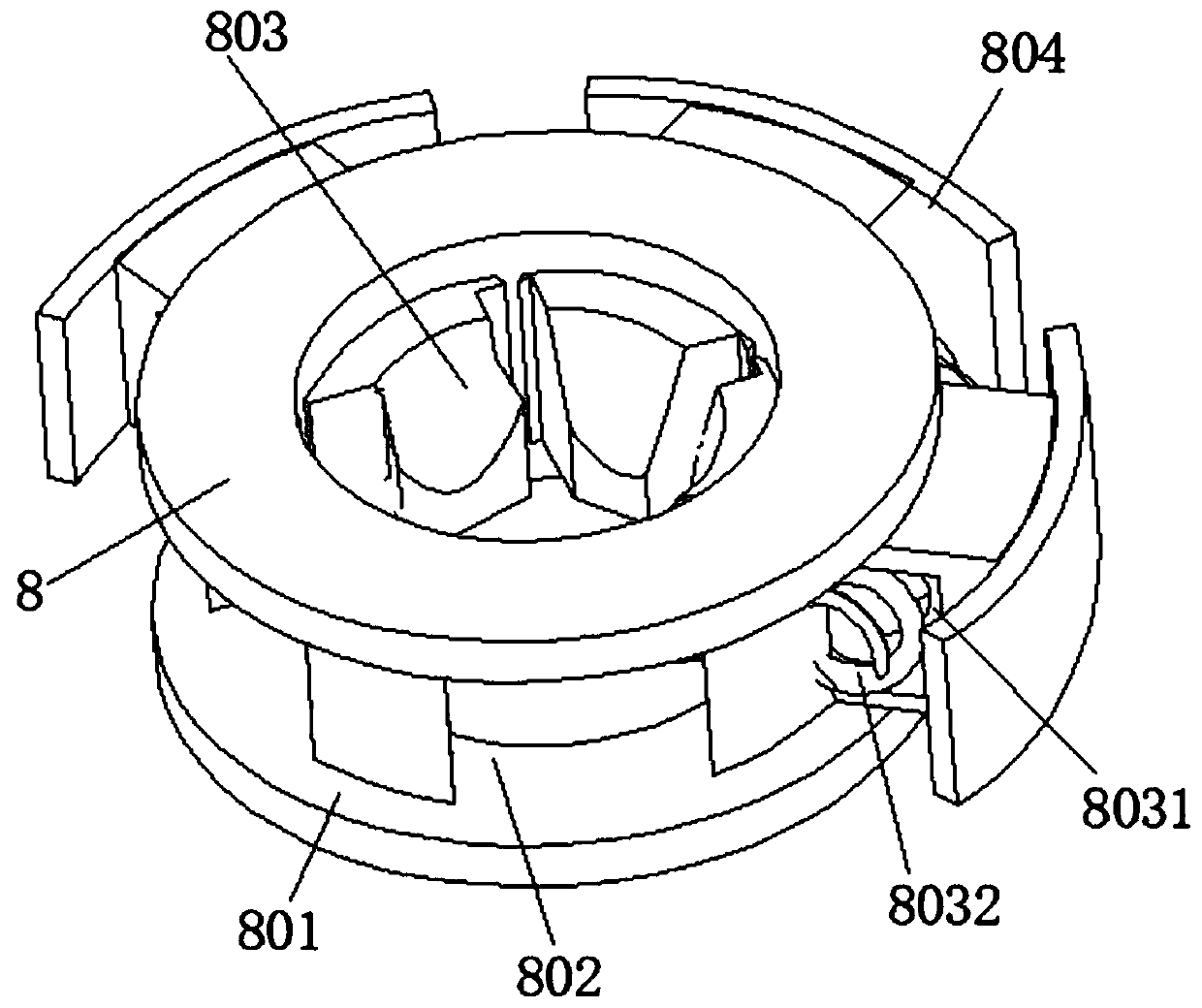
The invention discloses an automatic cable feeding device, which belongs to the technical field of cables. The automatic cable feeding device comprises a base; the top of the base is connected with two fixing frames; a fixing plate is connected between the two fixing frames; the outer wall of the fixing plate is connected with a transmission mechanism; rollers are connected to the bottom of the fixing frame; the rollers are connected with the transmission mechanism; the outer wall of the base is rotationally connected with a rotating seat; a cable part is connected between the roller and the rotating seat; an annular groove is dug in the outer wall of the rotating seat; a first through hole is dug in the inner wall of the annular groove; a moving block is slidably connected to the inner wall of the first through hole; a concave hole is dug in the moving block; an annular spring is connected to the inner wall of the concave hole and arranged on the inner wall of the annular groove; anda conical block is movably connected in the rotating seat. Through the rotating seat, cables of different sizes can be conveyed, the production cost is effectively reduced, the cable feeding structureis simple, and the working efficiency is conveniently improved.

Description

technical field [0001] The invention relates to the technical field of cables, in particular to an automatic cable feeding device. Background technique [0002] Electric power engineering, that is, projects related to the production, transmission and distribution of electric energy, also includes projects that use electricity as power and energy in various fields in a broad sense. Cables are used in the process. Cables are widely used. Common applications include power systems, information transmission systems, etc. Power information cables include local telephone cables, TV cables, optical cables, etc. Cables are composed of one or more A wire made of mutually insulated conductors and an outer insulating layer that transmits electricity or information from one place to another. [0003] At present, the wire ends commonly used in the field of electric power engineering often have to be stripped, and then pressed onto a metal joint for convenient connection between the wire ...

Claims


Application Information

Patent Timeline
Patent Type & Authority Applications(China)
IPC IPC(8): B65H51/10H02G1/12
CPCB65H51/10B65H2701/34H02G1/12
Inventor 顾建芳顾小荣吴云明王荣宋文金
Owner 浙江龙鹰光电科技有限公司
Why Eureka
Try Eureka