Detachable winding shaft structure

A reeling and detachable technology, applied in the field of detachable reeling structure, can solve the problem of time-consuming and labor-intensive

Active Publication Date: 2020-04-14
重庆巧琢工贸发展有限公司
View PDF5 Cites 8 Cited by
  • Summary
  • Abstract
  • Description
  • Claims
  • Application Information

AI Technical Summary

Problems solved by technology

In the existing sub-rolling device, the rotating shaft for winding small rolls is mostly designed in one piece, that is, multiple small rolls will be wound on the same rotating shaft, so it is time-consuming and labor-intensive when unloading

Method used


Image

  • Detachable winding shaft structure
  • Detachable winding shaft structure
  • Detachable winding shaft structure

Examples


Embodiment 1

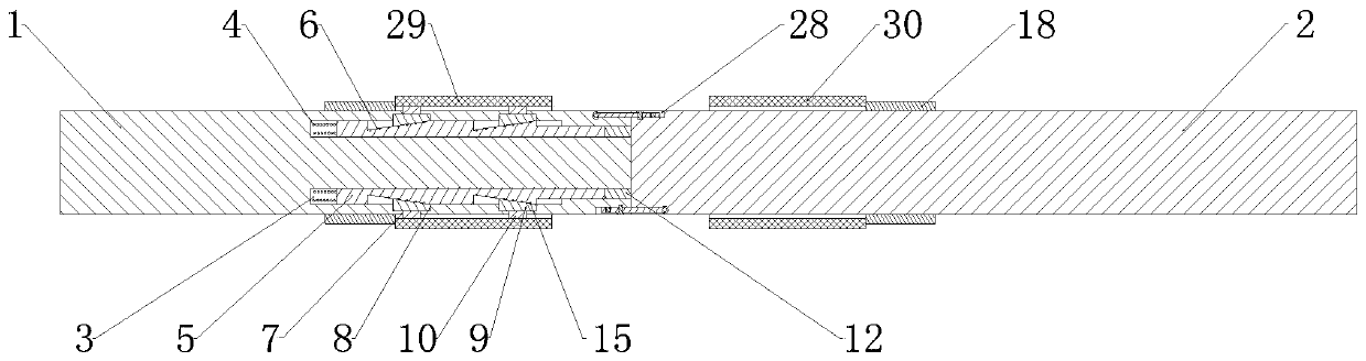
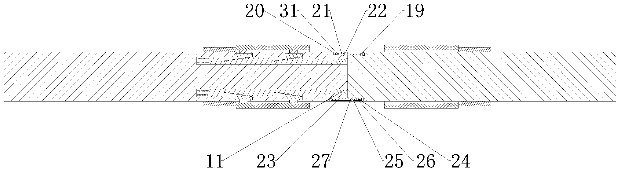
[0047] Such as Figure 1 to Figure 4 As shown, the detachable winding shaft structure includes half shaft A1 and half shaft B2, and half shaft B2 is detachably connected to half shaft A1 through a connecting component;

[0048] The inner ends of the half-shaft A1 and the half-shaft B2 are provided with a number of locking grooves 3 arranged in a ring. The locking groove 3 is connected with a locking rod 5 that can slide relative to the locking groove 3 through an elastic member 4. The locking rod 5 The top of 5 is provided with several jacking notch grooves 6, and the bottom surface of the jacking notch grooves 6 is arranged on an inclined plane, and the depth of the jacking notch grooves 6 is gradually deepened toward the direction close to the elastic member 4;

[0049] The outer ring surfaces of the semi-axis A1 and the semi-axis B2 are provided with telescopic notches corresponding to the number of jacking notch grooves 6. The telescopic notches have telescopic openings 7 ...

Embodiment 2

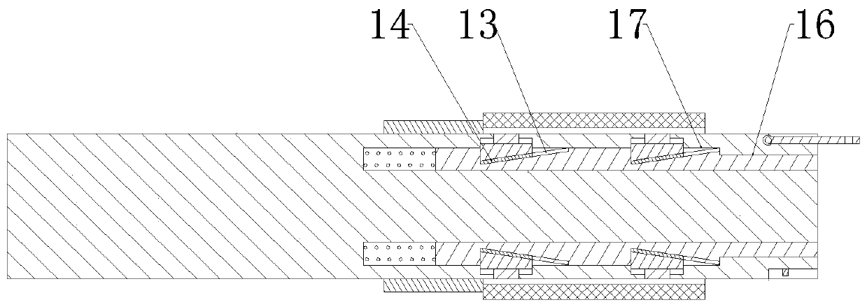
[0055] This embodiment makes the following further limitations on the basis of embodiment 1: the groove bottom of the jacking notch groove 6 is provided with a chute 13 with a small opening and a large inner cavity;

[0056] The bottom end of the jacking slider 9 is provided with a connecting protrusion 14 capable of slidingly fitting with the sliding groove 13 .

Embodiment 3

[0058] This embodiment is further defined as follows on the basis of Embodiment 1: the bottom surface of the jacking notch groove 6 is provided with a ball 15 capable of acting on the bottom end surface of the jacking slider 9 .


PUM


Abstract

The invention discloses a detachable winding shaft structure, which comprises a half shaft A and a half shaft B, wherein the half shaft B is detachably connected with the half shaft A through a connecting assembly; a plurality of annularly arranged locking grooves are formed in the inner side ends of the half shaft A and the half shaft B; telescopic notches corresponding to jacking notch grooves in number are formed in the outer ring surfaces of the half shaft A and the half shaft B; elastic pieces act on locking rods, so that the deepest part of each jacking notch groove can directly face a corresponding jacking sliding block, and the locking rods are located in the locking grooves respectively; and the inner side end of the half shaft B is provided with a plurality of jacking rods B which can be respectively placed in and matched with the plurality of locking grooves of the half shaft A. Through the arrangement of the locking rods and the jacking rods, the expansion arrangement of positioning bulges can be realized when the half shaft A and the half shaft B are connected, so that the positioning work of a winding drum is conveniently realized; and when the connecting assembly isunfastened, the positioning bulges can be accommodated, so that the discharging work of the winding drum is conveniently realized.

Description

technical field [0001] The invention relates to the technical field of packaging and bag making, in particular to a detachable winding shaft structure. Background technique [0002] Food packaging generally uses plastic packaging bags as the main product. Plastic packaging bags mostly include the following production process before making bags: printing (coating ink on the surface of the printing plate, and transferring the graphics on the printing plate to the surface of the printed material through pressure) → compounding (through a medium (such as Glue) to bond two or more layers of materials together) → ripening (accelerating the curing speed of the glue between materials), and then the plastic film for packaging bags can be formed, and then it can be divided into rolls. Rolling operation is to divide the large roll of cured plastic film into several small rolls so that the customer manufacturer can carry out subsequent bag making operations. In the existing winding de...

Claims


Application Information

Patent Timeline
Patent Type & Authority Applications(China)
IPC IPC(8): B65H75/22B65H75/24
CPCB65H75/22B65H75/242B65H2701/191
Inventor 雷波
Owner 重庆巧琢工贸发展有限公司
Why Eureka
Try Eureka