
Pressure reducing valve installed on liquefied petroleum gas steel cylinder valve

A technology of liquefied petroleum gas and cylinder valve, applied in the field of pressure reducing valve, can solve the problems of inconvenient disassembly, easy blockage of the intake pipe, air leakage, etc., to achieve the effect of enhancing sealing, avoiding potential safety hazards and improving quality

Active Publication Date: 2020-04-14
JIANGSU YONGFENG ELECTRICAL INSTR CO LTD
View PDF8 Cites 0 Cited by
  • Summary
  • Abstract
  • Description
  • Claims
  • Application Information

AI Technical Summary

Problems solved by technology

[0004] The purpose of the present invention is to provide a pressure reducing valve installed on the valve of the liquefied petroleum gas cylinder, to solve the problem that the current pressure reducing valve installed on the valve of the cylinder of liquefied petroleum gas proposed by the above background technology is mostly inconvenient to disassemble when in use, And after a long time of use, it is easy to cause air leakage, and at the same time it is inconvenient to filter the impurities in the liquefied gas, and it is easy to block the intake pipe.

Method used


Image

  • Pressure reducing valve installed on liquefied petroleum gas steel cylinder valve
  • Pressure reducing valve installed on liquefied petroleum gas steel cylinder valve
  • Pressure reducing valve installed on liquefied petroleum gas steel cylinder valve

Examples


Embodiment Construction

[0029] The following will clearly and completely describe the technical solutions in the embodiments of the present invention with reference to the accompanying drawings in the embodiments of the present invention. Obviously, the described embodiments are only some, not all, embodiments of the present invention. Based on the embodiments of the present invention, all other embodiments obtained by persons of ordinary skill in the art without making creative efforts belong to the protection scope of the present invention.

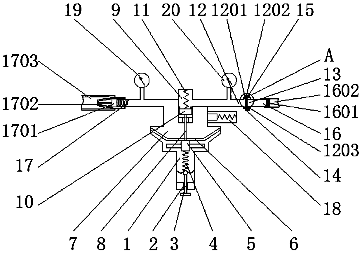
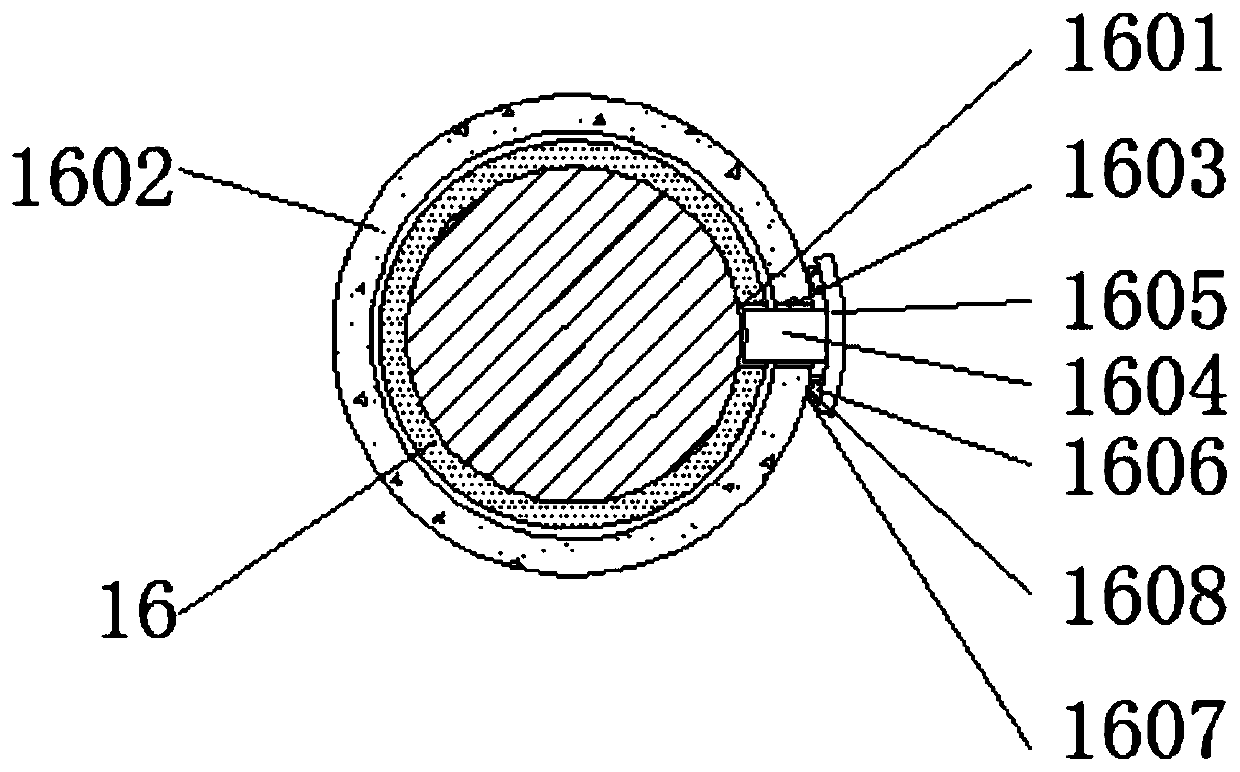
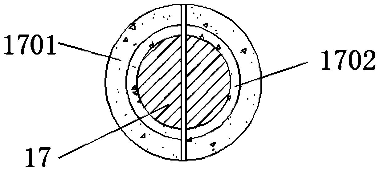
[0030] see Figure 1-4 , the present invention provides a technical solution: a pressure reducing valve installed on a liquefied petroleum gas cylinder valve, including a main body 1, a screw groove 2, a screw 3, a first spring 4, a spring pad 5, a transmission film 6, a low pressure Air chamber 7, push rod 8, high-pressure air chamber 9, movable door 10, second spring 11, first connecting pipe 12, second connecting pipe 13, flange 14, bolt 15, air inlet pipe ...


PUM


Abstract

The invention discloses a pressure reducing valve installed on a liquefied petroleum gas steel cylinder valve. The pressure reducing valve comprises a main body, wherein a rod groove is formed on oneside of the main body, a screw rod is arranged in the rod groove, a first spring is connected with the side, close to the main body, of the screw rod, a spring cushion block is fixed to a side, away from the screw rod, of the first spring, a transmission film is arranged on the side, away from the first spring, of the spring cushion block, and a low-pressure air chamber is formed in the side, close to the transmission film, of the main body. The pressure reducing valve installed on the liquefied petroleum gas steel cylinder valve is advantaged in that an insertion block is set, an air inlet pipe is made to rotate, the air inlet pipe is connected with a steel cylinder connecting pipe through a thread structure, when a first notch and a second notch are located on the same horizontal plane,the insertion block is moved into the first notch and the second notch to block the first notch and the second notch, and the situation that when the pressure reducing valve is used for a long time, athreaded structure formed by an air inlet pipe and a steel cylinder connecting pipe loosens, and fixation is unstable is avoided.

Description

technical field [0001] The invention relates to the technical field of pressure reducing valves, in particular to a pressure reducing valve installed on a cylinder valve of liquefied petroleum gas. Background technique [0002] The pressure reducing valve is a valve that reduces the inlet pressure to a certain required outlet pressure through adjustment, and relies on the energy of the medium itself to keep the outlet pressure automatically stable. Although the current pressure reducing valve installed on the liquefied petroleum gas cylinder valve There are many types and quantities, but the existing pressure reducing valve installed on the liquefied petroleum gas cylinder valve still has certain problems, which brings certain inconvenience to the use of the pressure reducing valve installed on the liquefied petroleum gas cylinder valve. [0003] However, most pressure reducing valves installed on liquefied petroleum gas cylinder valves are inconvenient to disassemble and as...

Claims


Application Information

Patent Timeline
Patent Type & Authority Applications(China)
IPC IPC(8): F17C13/04F16K27/00F16L15/08F16L23/024B01D29/05B01D35/04
CPCB01D29/05B01D35/04F16K27/00F16L15/08F16L23/024F17C13/04
Inventor 杨静
Owner JIANGSU YONGFENG ELECTRICAL INSTR CO LTD
Learn More