Supercharge Your Innovation With Domain-Expert AI Agents!

Rubber ball cleaning device capable of automatically replacing rubber balls

A technology for automatic replacement and cleaning of devices. It is used in cleaning heat transfer devices, non-rotating equipment cleaning, lighting and heating equipment. High efficiency and good cleaning effect

Inactive Publication Date: 2020-04-14
大唐郓城发电有限公司
View PDF8 Cites 0 Cited by
  • Summary
  • Abstract
  • Description
  • Claims
  • Application Information

AI Technical Summary

Problems solved by technology

[0003] The existing rubber ball cleaning device has shortcomings in use. The rubber ball itself is contaminated with more stains, resulting in low cleaning effect, and the rubber ball is not easy to replace. It needs to be shut down when replacing and removing impurities, which seriously affects the cleaning efficiency.

Method used


Image

  • Rubber ball cleaning device capable of automatically replacing rubber balls
  • Rubber ball cleaning device capable of automatically replacing rubber balls
  • Rubber ball cleaning device capable of automatically replacing rubber balls

Examples


Embodiment 1

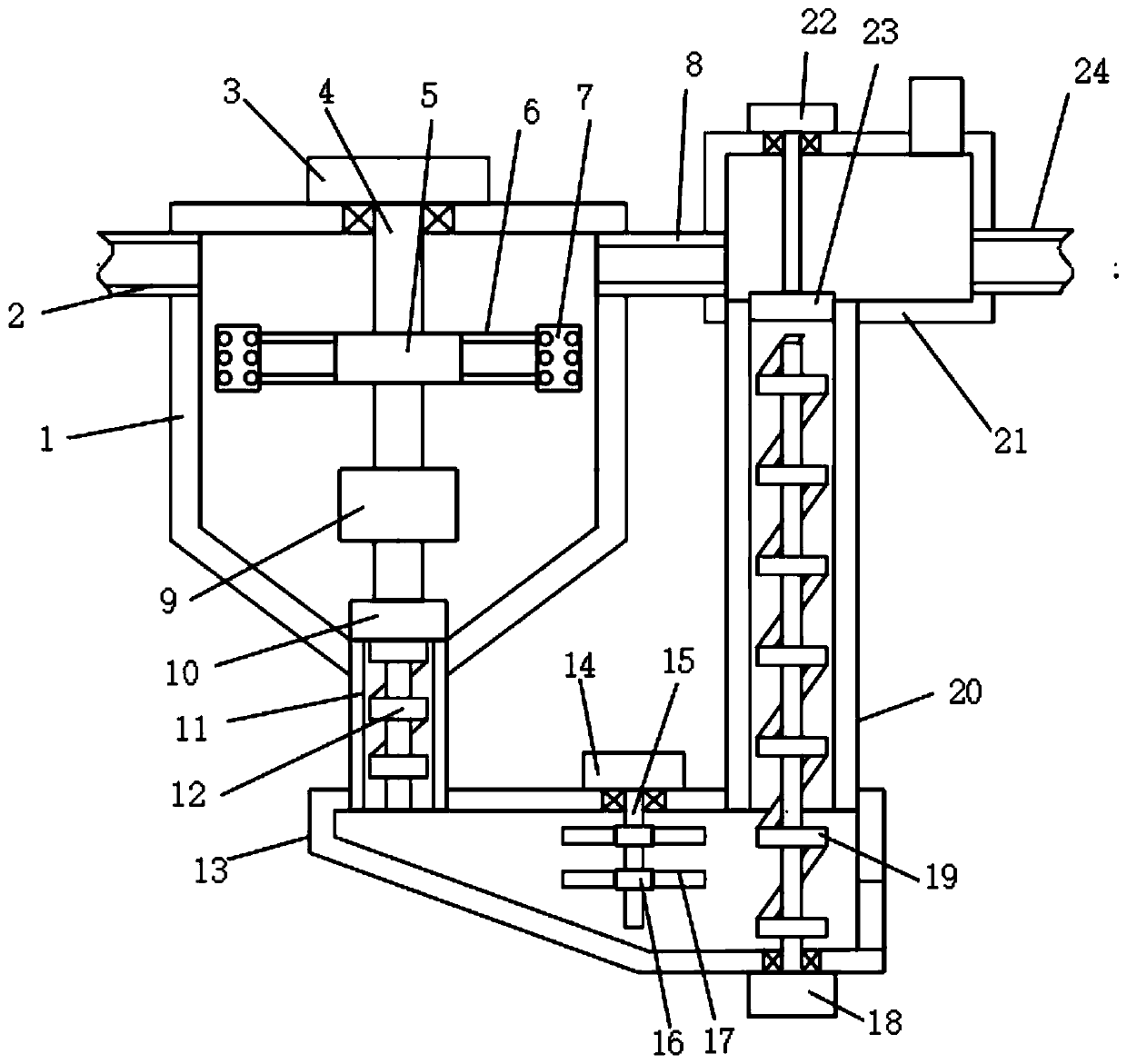
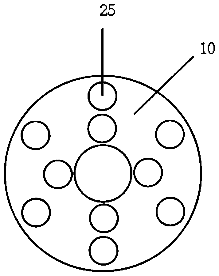
[0025] refer to Figure 1-2 , a rubber ball cleaning device that can automatically replace rubber balls, including a first housing 1, a first connecting pipe 8 runs through the side of the first housing 1, and a third housing 21 is fixed on the side of the first connecting pipe 8 , the bottom of the first housing 1 is provided with a second connecting pipe 11, the bottom of the second connecting pipe 11 is fixed with a second housing 13, and the top of the second housing 13 is fixed with a third Connecting pipe 20, the top of the third connecting pipe 20 is fixedly connected with the third housing 21, the top of the first housing 1 is equipped with the first motor 3, the output shaft of the first motor 3 is inserted into the inside of the first housing 1 and Connected with a reciprocating screw rod 4, the reciprocating screw rod 4 is connected with a threaded sleeve 5 through a thread sleeve, the side of the threaded sleeve 5 is welded with a bracket 6, and the end of the brac...

Embodiment 2

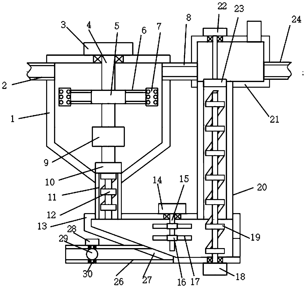
[0034] refer to Figure 2-4, a rubber ball cleaning device that can automatically replace rubber balls, including a first housing 1, a first connecting pipe 8 runs through the side of the first housing 1, and a third housing 21 is fixed on the side of the first connecting pipe 8 , the bottom of the first housing 1 is provided with a second connecting pipe 11, the bottom of the second connecting pipe 11 is fixed with a second housing 13, and the top of the second housing 13 is fixed with a third Connecting pipe 20, the top of the third connecting pipe 20 is fixedly connected with the third housing 21, the top of the first housing 1 is equipped with the first motor 3, the output shaft of the first motor 3 is inserted into the inside of the first housing 1 and Connected with a reciprocating screw rod 4, the reciprocating screw rod 4 is connected with a threaded sleeve 5 through a thread sleeve, the side of the threaded sleeve 5 is welded with a bracket 6, and the end of the brack...


PUM


Abstract

The invention discloses a rubber ball cleaning device capable of automatically replacing rubber balls. The device comprises a first housing, a first connecting pipe penetrates through the side surfaceof the first shell; a third shell is fixed to the side face of the first connecting pipe, a second connecting pipe is arranged at the bottom of the first shell, a second shell is fixed to the bottomof the second connecting pipe, a third connecting pipe is fixed to the end, away from the second connecting pipe, of the top of the second shell, and the top of the third connecting pipe is fixedly connected with the third shell. By arranging a first screw rod, a second screw rod, a first hydraulic cylinder, a second hydraulic cylinder, a first sealing plate and a second sealing plate, multiple batches of rubber balls can be circularly cleaned without shutdown by repeating the steps in the cleaning process, the cleaning effect is good, and the cleaning efficiency is high; and by arranging a slag discharging pipe, a fourth motor, a second rotating shaft and a sealing plate, shutdown for slag discharging is not needed during cleaning, and the cleaning efficiency is further improved.

Description

technical field [0001] The invention relates to the technical field of rubber ball cleaning, in particular to a rubber ball cleaning device capable of automatically replacing rubber balls. Background technique [0002] The rubber ball cleaning device is the best equipment for effectively cleaning the cooling pipe of the condenser during the operation of the steam turbine unit. The performance of the device directly affects the cleaning degree and heat transfer effect of the steam turbine condenser. [0003] The existing rubber ball cleaning device has shortcomings in use. The rubber ball itself is contaminated with more stains, resulting in low cleaning effect, and the rubber ball is not easy to replace. It needs to be shut down when replacing and removing impurities, which seriously affects the cleaning efficiency. Contents of the invention [0004] The purpose of the present invention is to solve the shortcomings in the prior art, and propose a rubber ball cleaning devi...

Claims


Application Information

Patent Timeline
IPC IPC(8): F28G1/12
CPCF28G1/12
Inventor 孙德新安宝宏杨腾
Owner 大唐郓城发电有限公司
Features
  • R&D
  • Intellectual Property
  • Life Sciences
  • Materials
  • Tech Scout
  • Unparalleled Data Quality
  • Higher Quality Content
  • 60% Fewer Hallucinations
Learn More