
Continuous feeding type full-automatic testing machine

A fully automatic testing and feeding technology, which is applied in the direction of optical testing flaws/defects, measuring devices, analyzing materials, etc., can solve the problems of detection interference, large number of parts, and reduce detection accuracy, so as to achieve the effect of improving accuracy

Pending Publication Date: 2020-04-14
沅陵县品诺鼎电子科技有限公司
View PDF0 Cites 0 Cited by
  • Summary
  • Abstract
  • Description
  • Claims
  • Application Information

AI Technical Summary

Problems solved by technology

[0002] Some existing mechanical parts need to be inspected for appearance and size after processing. In the past, manual inspection was mainly used, but the number of parts is very large. Manual inspection can only be random inspection, and there will be many loopholes in random inspection, so Now most of them are detected by optical instruments, and the detection efficiency is greatly improved.
[0003] Existing automatic testing machines use vibrating discs to feed materials, and then use optical cameras to detect each product, but because the vibrating discs are fed continuously, the parts are all next to each other, so in the lens of the camera There may be multiple parts under the test, which will interfere with the detection and reduce the accuracy of the detection

Method used


Image

  • Continuous feeding type full-automatic testing machine
  • Continuous feeding type full-automatic testing machine
  • Continuous feeding type full-automatic testing machine

Examples


Embodiment Construction

[0025] The following will clearly and completely describe the technical solutions in the embodiments of the present invention with reference to the accompanying drawings in the embodiments of the present invention. Obviously, the described embodiments are only some, not all, embodiments of the present invention. Based on the embodiments of the present invention, all other embodiments obtained by persons of ordinary skill in the art without making creative efforts belong to the protection scope of the present invention.

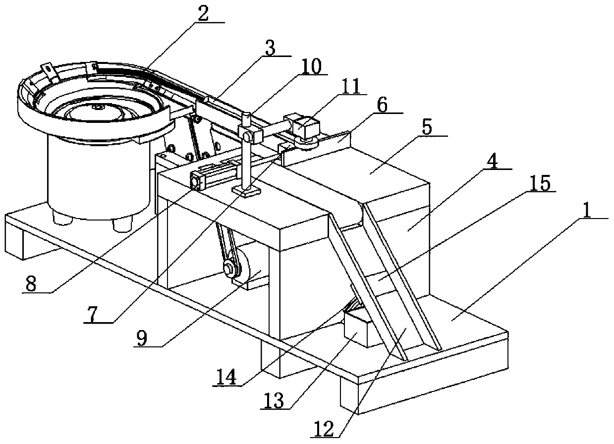
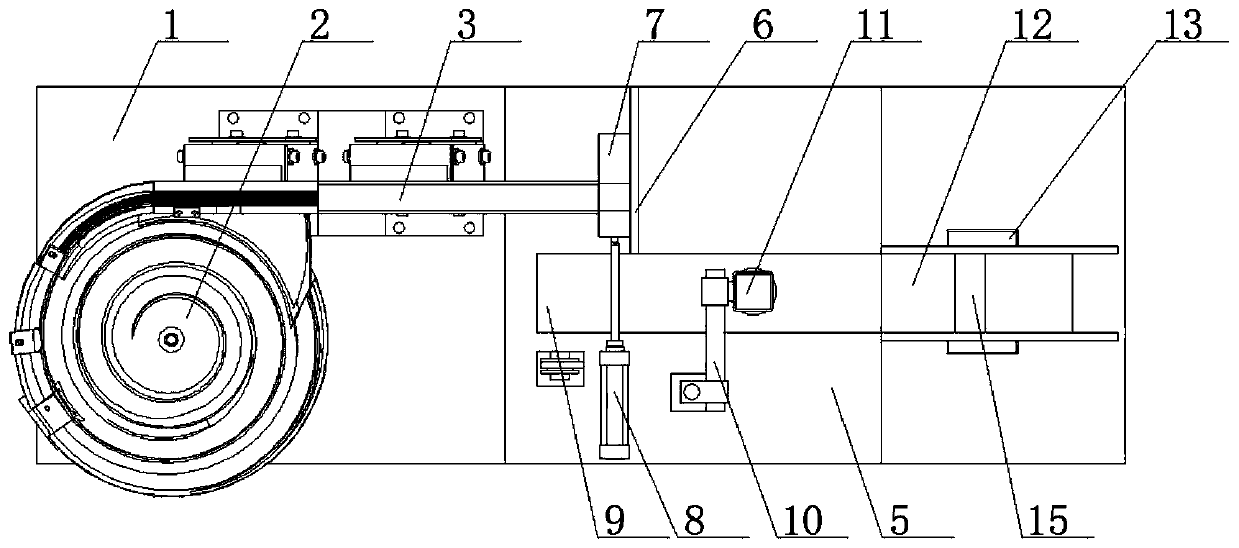
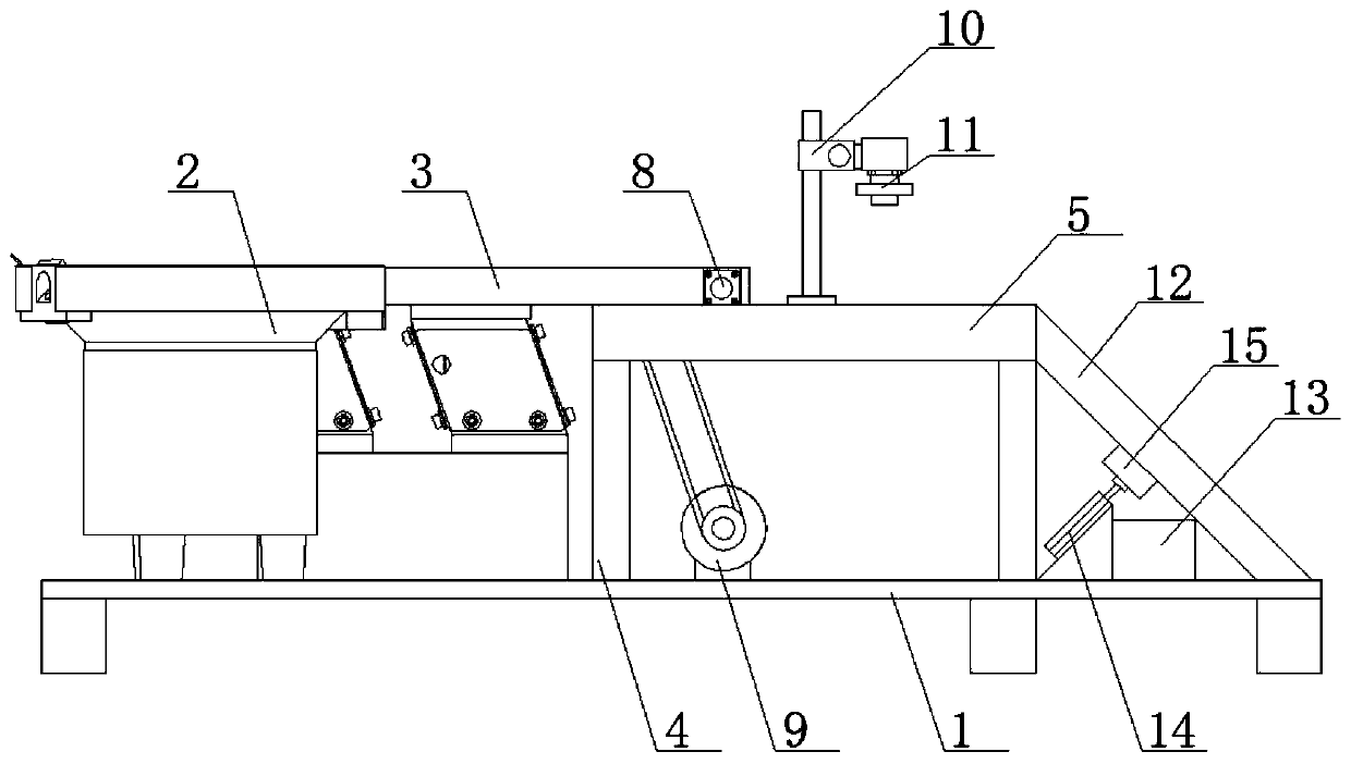
[0026] see Figure 1-6 , a continuous feeding type automatic testing machine, including a support base 1, a vibration plate 2 is fixedly installed on one side of the top of the support base 1, the outlet of the vibration plate 2 is fixedly connected with a connecting channel 3, and the top of the support base 1 is fixedly installed with two Two mutually symmetrical supporting side plates 4, the tops of the two supporting side plates 4 are fixedly equipped with...


PUM


Abstract

The invention relates to the technical field of detection instruments, and discloses a continuous feeding type full-automatic testing machine, which comprises a supporting base, and a vibration disc is fixedly installed on one side of the top of the supporting base. According to the continuous feeding type full-automatic testing machine, through mutual cooperation of a fixed baffle plate, a movingmechanism and a thin cylinder, parts in a connecting channel enter a placing groove through vibration; the fixed baffle plate blocks the parts in the placing groove, and the thin cylinder is startedto pull the moving mechanism to move towards a conveyor belt; when the placing groove moves to the position above the conveyor belt, the fixed baffle plate does not block the parts in the placing groove, and at the moment, the parts in the placing groove slide to the top of the conveyor belt, and the parts in the connecting channel are blocked by a movable baffle plate; the movable baffle plate makes contact with the connecting channel all the time to prevent the parts in the connecting channel from falling off, and therefore, an industrial camera can only detect one single part every time, and the detection accuracy is improved.

Description

technical field [0001] The invention relates to the technical field of testing instruments, in particular to a continuous feeding type full-automatic testing machine. Background technique [0002] Some existing mechanical parts need to be inspected for appearance and size after processing. In the past, manual inspection was mainly used, but the number of parts is very large. Manual inspection can only be random inspection, and there will be many loopholes in random inspection, so Now most of them are detected by optical instruments, and the detection efficiency is greatly improved. [0003] Existing automatic testing machines use vibrating plate feeding, and then use optical cameras to detect each product, but because the feeding of vibrating plate is continuous, the parts are all next to each other, so in the lens of the camera There may be multiple parts under the test, which will interfere with the test and reduce the accuracy of the test. Contents of the invention ...

Claims


Application Information

Patent Timeline
IPC IPC(8): G01B11/00G01N21/01G01N21/88
CPCG01B11/00G01N21/01G01N21/88
Inventor 张武代德爱
Owner 沅陵县品诺鼎电子科技有限公司
Learn More