A detection device applied to bridge cracks

A technology for detecting devices and bridges, which is used in measurement devices, optical testing of flaws/defects, and material analysis by optical means, etc., can solve problems such as small application scope, damage to the integrity of bridge structures, and potential safety hazards.

Active Publication Date: 2021-04-23
济南工程职业技术学院
View PDF5 Cites 0 Cited by
  • Summary
  • Abstract
  • Description
  • Claims
  • Application Information

AI Technical Summary

Problems solved by technology

Under the action of external factors, bridges often deform, leading to cracks or even damage. More than 90% of the damage of concrete bridges is caused by cracks. Engineering practice and theoretical analysis show that almost all concrete components work with cracks, and some cracks Small, even invisible to the naked eye (<0.05mm), generally there is no great harm to the normal use of the structure, and its existence is allowed, but some cracks are constantly generated and expanded under the action of load or external physical and chemical factors. Cracks above 0.20-0.30 mm will directly destroy the structural integrity of the bridge, cause concrete carbonization, peeling of the protective layer, and corrosion of steel bars, and form mechanical discontinuities inside the bridge, which will increase the bearing capacity of the bridge. It is greatly reduced, and even collapse accidents occur in severe cases, which will affect the normal use of the bridge; the traditional bridge crack detection method is mostly carried out by the staff with hand-held detectors. This detection method is time-consuming and laborious, and the work efficiency is low. Cracks on the bottom surface require workers to hang on the outside of the bridge to detect, which brings a greater safety hazard to the staff
[0003] After searching, the Chinese invention patent with the application number of 201810859789.4 discloses an automatic detection method for bridge cracks, and specifically discloses that the detection method is based on an automatic detection device for bridge cracks. The automatic detection device for bridge cracks includes a bottom plate and an automatic flaw detection mechanism. , Bridge deck detection mechanism and lifting mechanism, the bottom of the base plate is provided with a walking device, the automatic flaw detection mechanism includes a support seat, a flaw detection component on the top surface of the guardrail, a flaw detection component on the side wall of the guardrail and a flaw detection component on the bottom surface of the bridge, the flaw detection component on the top surface of the guardrail includes There is a U-shaped support plate and a fixed block. The bottom of the fixed block is provided with a mounting groove, and the flaw detection component on the top surface of the guardrail is installed in the mounting groove. After research, it is found that although it can realize flaw detection through the flaw detection component on the top surface of the guardrail and the side wall of the guardrail The component can perform flaw detection on the top surface and side wall of the guardrail respectively, the detection angle of the fourth detection probe can be changed through the angle adjustment part, and the flaw detection component on the bottom surface of the bridge can automatically detect flaws on the bottom surface of the bridge, avoiding workers There are potential safety hazards caused by manual flaw detection on the bottom of the bridge, but there are still the following defects: the device detects cracks on the side wall of the guardrail through the flaw detection component of the side wall of the guardrail, but only the outer side of the side wall of the guardrail is detected, and the inner side of the side wall of the guardrail is used This device cannot be detected, and the scope of application is small; when detecting the surface of the bridge, the electric push rod is used to push the connecting block to a certain distance according to the width of the bridge, so that the extension plate slides out of the chute for a certain distance, and passes several fourth detections. The probe detects the surface of the bridge, and the cooperation between the electric push rod and several fourth detection probes detects the length and width direction of the bridge surface. There is a gap between them and the placement plate cannot be moved in the length direction, resulting in some gaps on the bridge surface not being detected, which reduces the working efficiency of the device

Method used


Image

  • A detection device applied to bridge cracks
  • A detection device applied to bridge cracks
  • A detection device applied to bridge cracks

Examples


Embodiment Construction

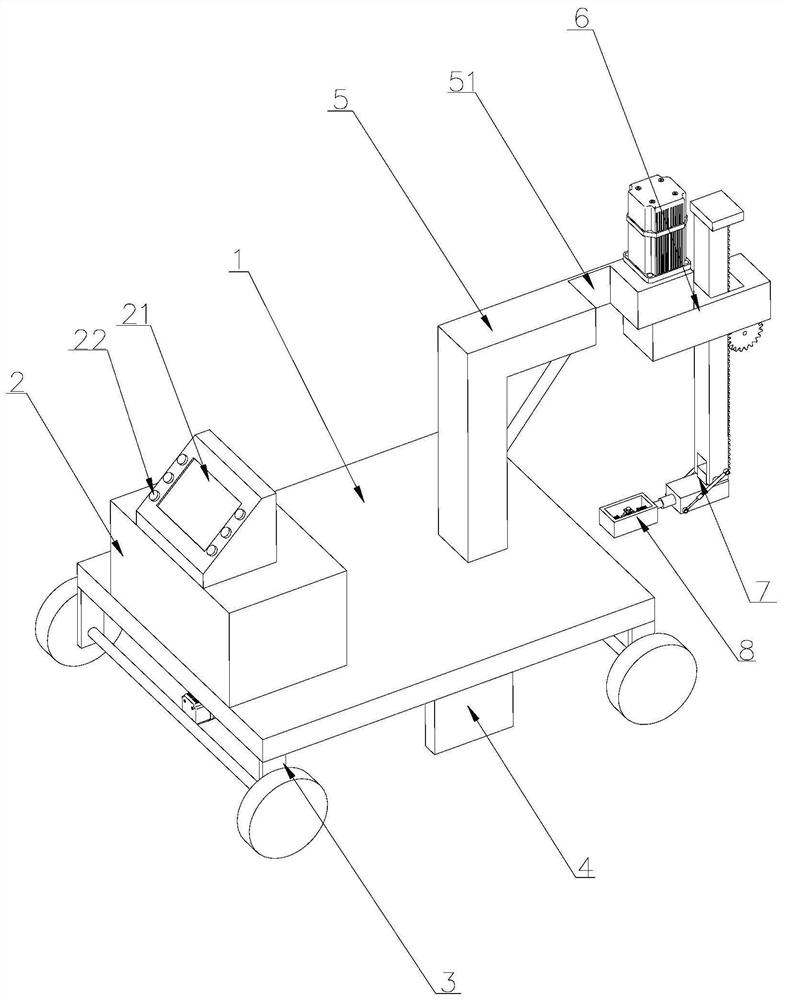
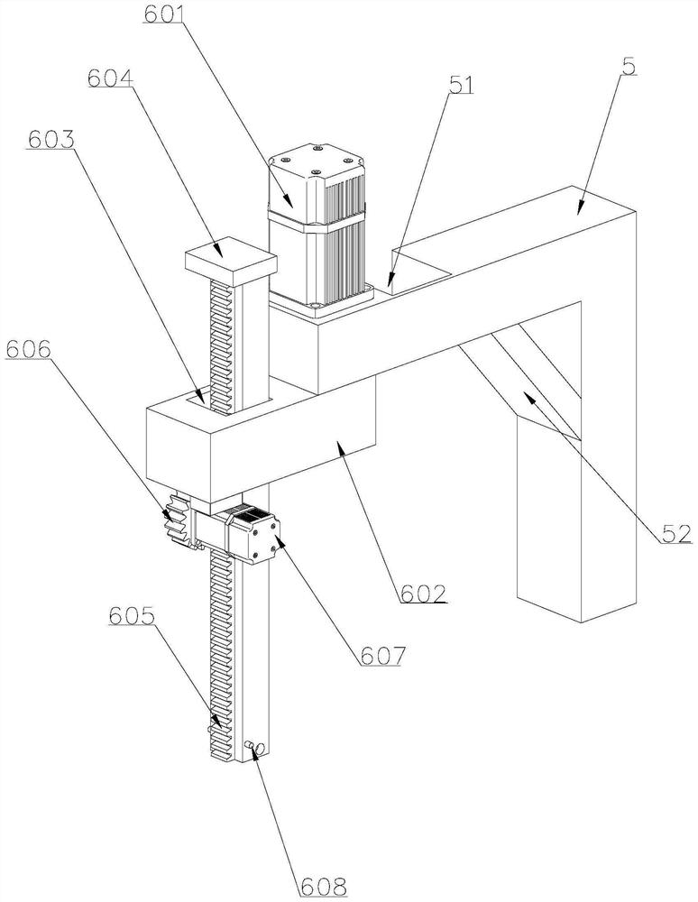
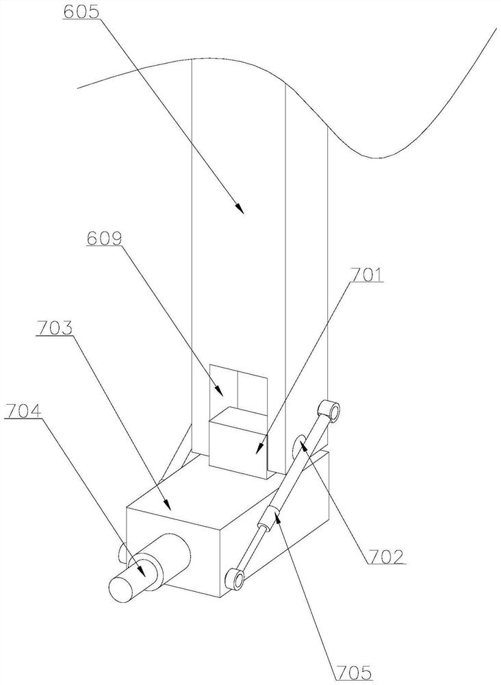
[0031] Attached below Figure 1-8 , clearly and completely describe the technical solutions in the embodiments of the present invention, obviously, the described embodiments are only some of the embodiments of the present invention, not all of them. Based on the embodiments of the present invention, all other embodiments obtained by persons of ordinary skill in the art without making creative efforts belong to the protection scope of the present invention.

[0032] In describing the present invention, it should be understood that the terms "longitudinal", "transverse", "upper", "lower", "front", "rear", "left", "right", "vertical", The orientations or positional relationships indicated by "horizontal", "top", "bottom", "inner", "outer", etc. are based on the orientations or positional relationships shown in the drawings, and are only for the convenience of describing the present invention, rather than indicating or It should not be construed as limiting the invention by imply...


PUM


Abstract

The invention discloses a detection device for cracks in bridges, comprising a flat plate, a first flaw detection device, and a second flaw detection device. A control box is arranged on one side above the top of the flat panel. The second flaw detection device of the present invention detects cracks on the inside and outside of the side wall of the guardrail by changing different angles through the rotating lifting device, and adjusts the angle of the second flaw detection device through the angle adjustment device to detect cracks on the bottom of the bridge. The inner side and outer side of the wall and the bottom of the bridge are all tested by the second flaw detection device, which reduces the production and use costs and improves the scope of application of the device. The first flaw detection device can move in the length and width directions of the surface of the bridge to realize There is no dead angle detection on the surface of the bridge, which improves the working efficiency of the device.

Description

technical field [0001] The invention belongs to the technical field of bridge detection, in particular to a detection device applied to bridge cracks. Background technique [0002] A bridge is a building that is erected on rivers, lakes and seas so that vehicles and pedestrians can pass smoothly. Under the action of external factors, bridges often deform, leading to cracks or even damage. More than 90% of the damage of concrete bridges is caused by cracks. Engineering practice and theoretical analysis show that almost all concrete components work with cracks, and some cracks Small, even invisible to the naked eye (<0.05mm), generally there is no great harm to the normal use of the structure, and its existence is allowed, but some cracks are constantly generated and expanded under the action of load or external physical and chemical factors. Cracks above 0.20-0.30 mm will directly destroy the structural integrity of the bridge, cause concrete carbonization, peeling of the...

Claims


Application Information

Patent Timeline
Patent Type & Authority Patents(China)
IPC IPC(8): G01N21/01G01N21/95
CPCG01N21/01G01N21/95
Inventor 肖明和
Owner 济南工程职业技术学院
Why Eureka
Try Eureka