Optical fiber micro-air-cavity photoacoustic cell, preparation method and dissolved gas detection method
A technology of dissolved gas and photoacoustic cell, which is applied in the direction of color/spectral characteristic measurement, measuring device, and material analysis through optical means, which can solve the problem of increasing the time for dissolved gas to diffuse into the photoacoustic cell, increasing the complexity and volume of the system , reduce the detection speed of the system, and achieve the effects of low cost, simple preparation method, and reduced performance damage
- Summary
- Abstract
- Description
- Claims
- Application Information
AI Technical Summary
Problems solved by technology
Method used
Image
Examples
Embodiment 1
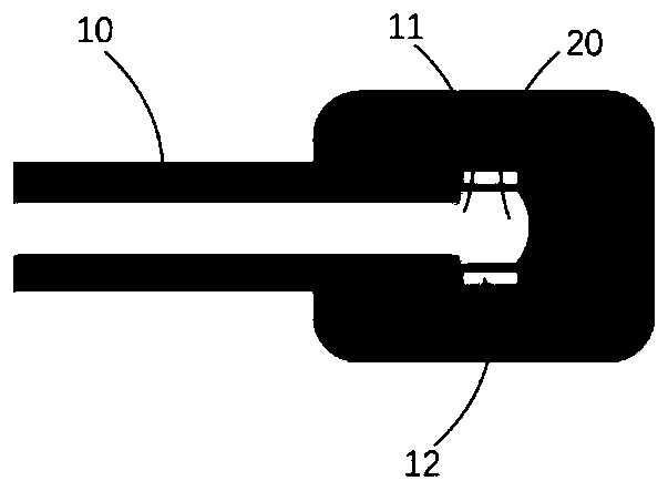
[0031] This embodiment discloses a photoacoustic cell with an optical fiber micro-air cavity. see figure 1 , figure 1 It is a schematic structural diagram of the optical fiber micro-air cavity photoacoustic cell of this embodiment. The optical fiber micro-air cavity photoacoustic cell of the embodiment of the present invention includes a transmission optical fiber 10, a quartz capillary 12, and a micro-air cavity 20;
[0032] Wherein, the transmission optical fiber 10 and the quartz capillary 12 are welded to form a fiber-capillary microstructure, the end face of the fiber-capillary microstructure is coated with a light-absorbing material 11, the transmission fiber 10 and the quartz capillary 12 are immersed in the liquid, and the micro air cavity 20 is located in the quartz capillary 12 Inside, the micro-air cavity 20 forms a Fabry-Perot cavity; the interface between the end face of the transmission fiber 10 and the liquid and the interface between the micro-air cavity 20 an...
Embodiment 2
[0046] This embodiment further proposes a method for preparing an optical fiber micro-air cavity photoacoustic cell, see further figure 2 , figure 2 It is a schematic diagram of the preparation method of the optical fiber micro-air cavity photoacoustic cell in this embodiment, and the specific steps are as follows:
[0047] Step S1, making a smooth end face on one end of the transmission optical fiber 10 with an optical fiber cutter;
[0048] Step S2. Splicing a section of quartz capillary 12 on the end face of the transmission optical fiber 10 through an optical fiber fusion splicer; under microscope observation, adjust the position of the cutting knife and the fusion point through a high-precision displacement platform, and control the length of the cut quartz capillary 12 to form an optical fiber - capillary microstructure;
[0049] Step S3, coating a layer of light-absorbing material 11 on the end surface of the fiber-capillary microstructure (in this embodiment, the l...
Embodiment 3
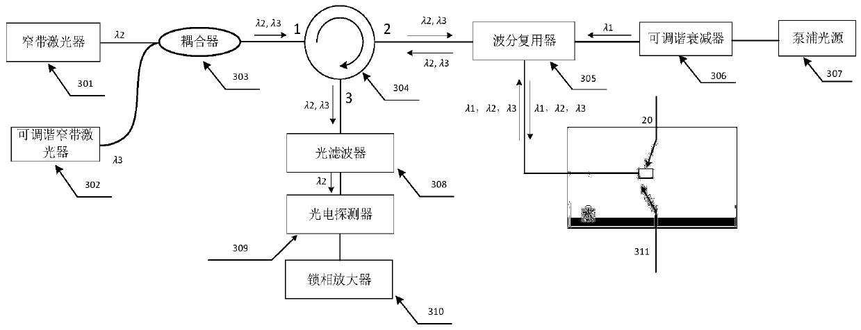
[0058] This embodiment further proposes a method for photoacoustic gas measurement using the optical fiber micro-air cavity photoacoustic cell produced by the above preparation method, see further image 3 , image 3 It is a schematic diagram of signal demodulation during the gas detection process of the optical fiber micro-air cavity photoacoustic cell according to the embodiment of the present invention, and the specific steps are as follows:
[0059] Step T1, the λ emitted from the pumping light source 307 1 The wavelength heating light reaches the λ of the wavelength division multiplexer 305 through the tunable optical attenuator 306 1 Wavelength input port; λ emitted by narrowband laser 301 2 The wavelength probe light and the lambda emitted by the tunable narrowband laser 302 3 The wavelength pumping light is transmitted from the first port 1 of the circulator 304 to the second port 2 after passing through the coupler 303, and reaches the λ of the wavelength division ...
PUM
| Property | Measurement | Unit |
|---|---|---|
| Outer diameter | aaaaa | aaaaa |
| Aperture | aaaaa | aaaaa |
| Length | aaaaa | aaaaa |
Abstract
Description
Claims
Application Information
 - R&D
- Intellectual Property
- Life Sciences
- Materials
- Tech Scout
- Unparalleled Data Quality
- Higher Quality Content
- 60% Fewer Hallucinations
Browse by: Latest US Patents, China's latest patents, Technical Efficacy Thesaurus, Application Domain, Technology Topic, Popular Technical Reports.
© 2025 PatSnap. All rights reserved.Legal|Privacy policy|Modern Slavery Act Transparency Statement|Sitemap|About US| Contact US: help@patsnap.com


