
Display screen capable of being spliced, adjusted and used

A display and screen technology, applied in the field of display, can solve the problems of broken display, unreliable fixed position, sliding and breaking of the display screen, etc., to achieve the effect of simple operation, ensuring that it will not fall and break, and increase labor intensity

Active Publication Date: 2020-04-14
深圳市颖网科技股份有限公司
View PDF9 Cites 3 Cited by
  • Summary
  • Abstract
  • Description
  • Claims
  • Application Information

AI Technical Summary

Problems solved by technology

[0003] However, the existing display screens have the following problems in the process of temporary splicing and use. a. It is necessary to manually fix the spliced ​​display screens with the help of clamps. The stability of manual fixation with clamps is poor, and the fixing position is not reliable, which may easily cause the display screens to slip and break. , and when the fixture is used to fix the display screen, it directly acts on the surroundings of the display screen, which affects the effect of the combined use of the display screen. Broken, and manual use of fixtures to splicing and fixing the display screen is complicated, disassembly is troublesome, and the labor intensity of operators is increased
[0004] For the current technical problems in the splicing of display screens, personnel in related technical fields have made adaptation improvements after research, such as the Chinese utility model patent No. 2018210021671, which is a splicable display screen that makes The two display frames fit together more closely, but the above-mentioned problems in the splicing of the display are not mentioned

Method used


Image

  • Display screen capable of being spliced, adjusted and used
  • Display screen capable of being spliced, adjusted and used
  • Display screen capable of being spliced, adjusted and used

Examples


Embodiment Construction

[0023] The embodiments of the present invention will be described in detail below with reference to the accompanying drawings, but the present invention can be implemented in many different ways defined and covered by the claims.

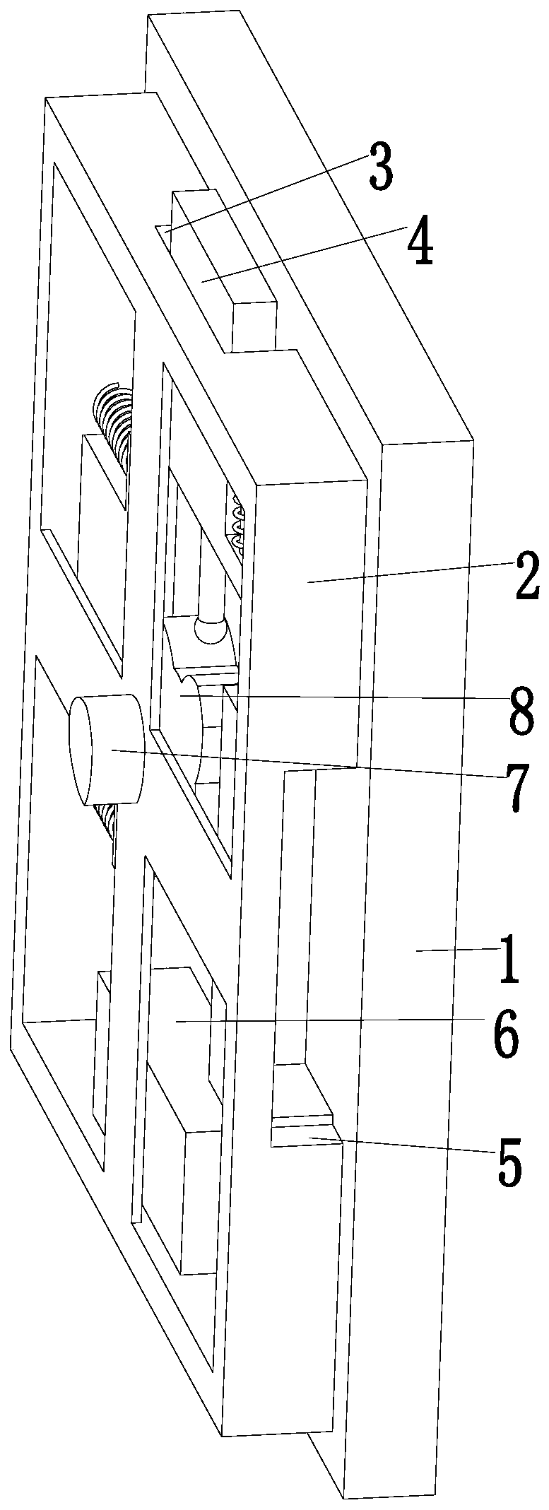
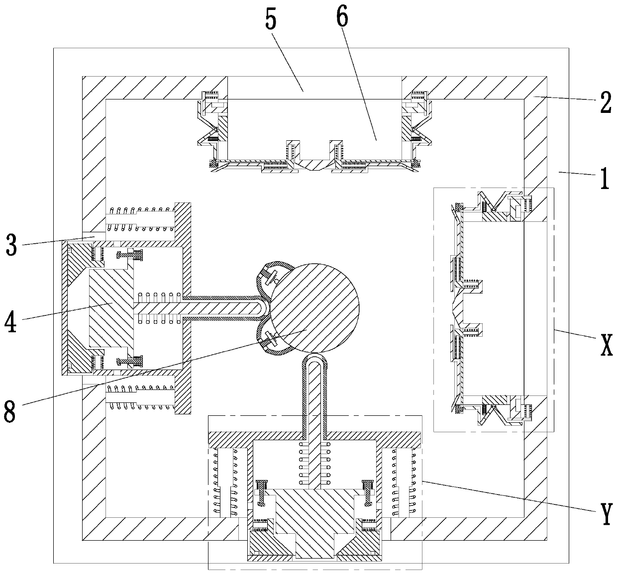
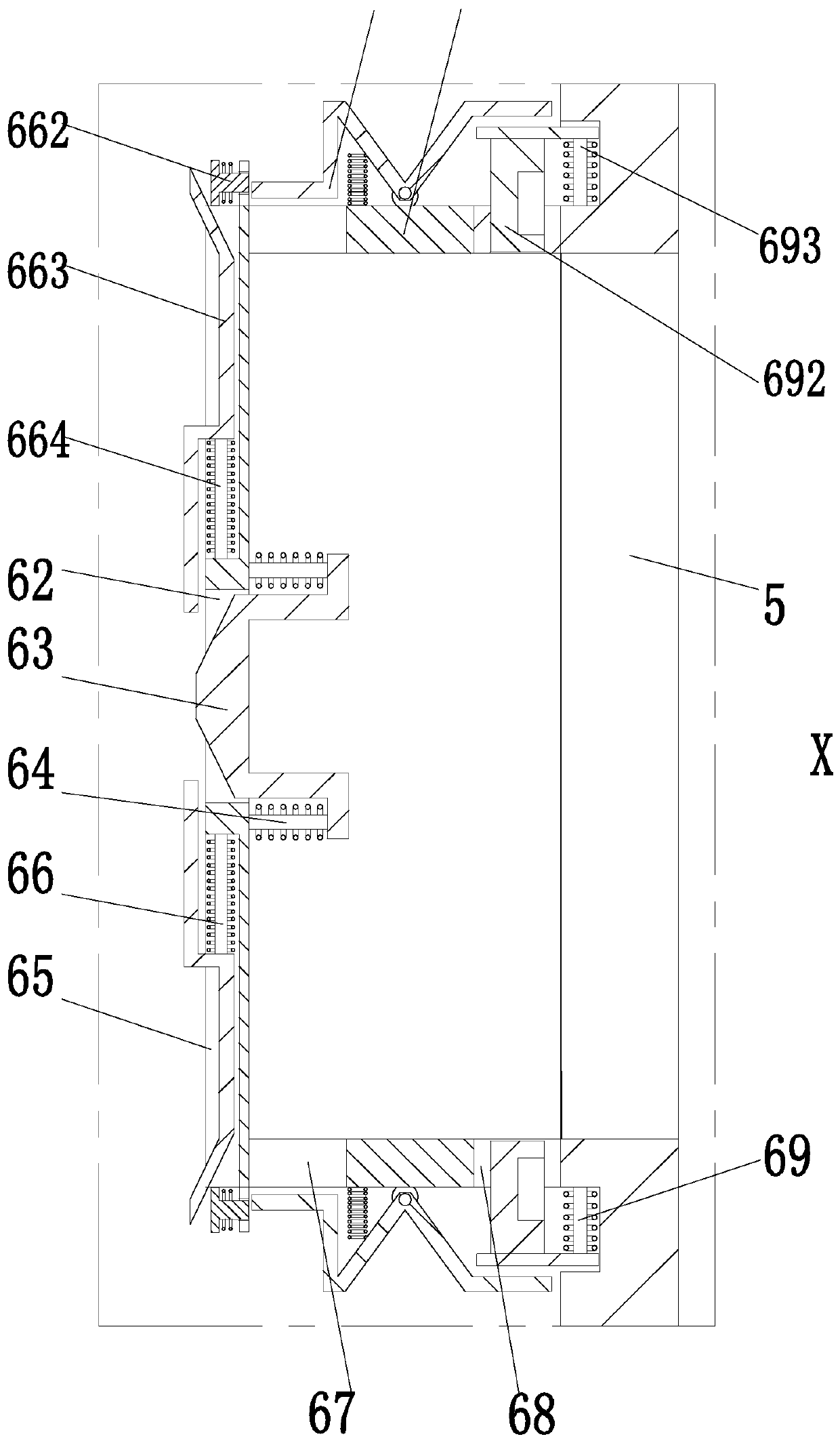
[0024] like Figure 1 to Figure 5 As shown, a display screen that can be spliced ​​and adjusted includes a screen body 1. The screen body 1 is installed on a splicing frame 2. The splicing frame 2 has a rectangular structure. The left end and the lower end of the splicing frame 2 are provided with through slots 3. A threading mechanism 4 is arranged in the threading slot 3, and a connecting groove 5 is arranged on the right end and the lower end of the splicing frame 2, and a connecting mechanism 6 is arranged in the connecting groove 5, and a splicing motor 7 is installed on the middle part of the splicing frame 2 through a motor seat, and splicing A rotating part 8 is installed on the output shaft of the motor 7; after the display screen to be spl...


PUM


Abstract

The invention relates to a display screen capable of being spliced, adjusted and used. The display screen comprises a screen body, the screen body is installed on a splicing frame, the left end and the lower end of the splicing frame are provided with inserting grooves, an inserting mechanism is arranged in the inserting grooves, connecting grooves are formed in the right end and the lower end ofthe splicing frame, and a connecting mechanism is arranged in the connecting grooves. According to the invention, the following problems of existing conventional display screen in the temporary splicing use process can be solved: a, a spliced display screen needs to be fixed manually by virtue of a clamp, the stability is poor when the clamp is manually adopted for fixing, a fixing position is unfirm, the display screen is liable to slide down and break, and when the clamp is used for fixing the display screen, the clamp directly acts on the periphery of the display screen, the effect of the display screen after combined use is affected; a, the clamp is manually used for directly clamping and locking the display screen, the display screen is prone to being broken due to too large force, and the operation of manually using the clamp for splicing and fixing the display screen is complex.

Description

technical field [0001] The invention relates to the technical field of display screens, in particular to a display screen that can be spliced ​​and adjusted for use. Background technique [0002] There is no unified statement on the concept of the display screen, but the understanding of it is mostly the same. As the name suggests, it should be a display tool that displays certain electronic files on the screen through a specific transmission device and then reflects them to the human eye, especially at present. Social display screens have become the main carrier of information dissemination. In outdoor activities or occasions where the crowd is relatively concentrated, splicing the display screens together to convey information to the crowd is a relatively common means at present. [0003] However, the existing display screens have the following problems in the process of temporary splicing and use. a. It is necessary to manually fix the spliced ​​display screens with the h...

Claims


Application Information

Patent Timeline
Patent Type & Authority Applications(China)
IPC IPC(8): G09F9/302
CPCG09F9/3026
Inventor 宋丰艾
Owner 深圳市颖网科技股份有限公司
Learn More