Tower lifting stand system

a technology for lifting stands and towers, applied in the direction of towers, buildings, constructions, etc., can solve the problems of unattended and without much maintenance, increased clearance, and stress on transmission lines, so as to increase the voltage, avoid the effect of high maintenance costs and increase the exposur

Active Publication Date: 2013-01-10
WALBRIDGE EQUIP INSTALLATION
View PDF17 Cites 29 Cited by
  • Summary
  • Abstract
  • Description
  • Claims
  • Application Information

AI Technical Summary

Benefits of technology

[0002]Transmission towers are used to provide a mechanism for carrying high voltage power lines throughout an electrical power grid. Typical transmission towers are aligned in a predetermined path and are placed within a power grid in accordance with the needs and demands of a population geographically located within the grid. Over fifty years ago it became customary to erect transmission towers across our country, which in large part have gone unattended and without much maintenance.
[0003]Transmission lines are typically secured to the upper portion of transmission towers using insulators, which allow the lines to be stretched from tower to tower. The transmission lines extend for miles and they drape from transmission tower to tower. Over time the transmission lines have become stressed due to increased exposure to environmental conditions and largely because the power companies have increased the voltage being transmitted through the grid system. This increase in voltage is due to increased consumer demand due to population growth and industry growth over the last century. Larger agricultural equipment has contributed to further decreased clearances and fatalities have resulted due to insufficient ground clearance.
[0004]One of the problems with transmission lines as they age is that they have a tendency of expanding and contracting, which over the years has caused them to generally stretch and increase in overall length since they have a tendency to expand more than they contract. When the length of the line increases, that extra length has to be absorbed within the power grid system somehow. The end result is that the newly extended length of lines is accumulated between each transmission tower in the form of increased line sag. Over time line sag can amount to several feet of vertical distance in drop of the line towards the earth. In some instances, it has been known that the transmission lines sag so severely that they physically interfere with the environment below where the transmission lines are hanging. It is desirable to eliminate this concern for safety reasons as well as to comply with governmental regulations. Accordingly, it would be desirable to provide a system and method of increasing the distance between the ground and sagging transmission lines that are becoming abundant in our power grid.
[0005]One method for resolving the aforementioned problem is to deliver a large crane to a job site where the transmission tower resides and use the crane to physically lift the tower up in the air so as to provide room under the previously existing transmission tower. Once the tower is raised, a vertical extension section can then be permanently installed. This process raises up the tower which in turn lifts up the transmission lines so that they are off of the ground. The problem, however, with this approach is that cranes are very expensive to operate on an hourly basis, which makes them cost prohibitive to use exclusively for maintaining the thousands of towers that are in our power grid. Further, because the type of crane that is needed to do this job is so large, the installation and setup process requires substantial resources and manpower to even stage the crane at the job site. This is because large lift cranes often require special beds to be laid down on the ground in advance of the crane being delivered to the job site which often is in rural areas having limited accessibility. The effort alone to get a large crane to an individual tower location is very labor intensive and often cost prohibitive. Thus, it would be preferred to avoid the use of cranes for this transmission tower maintenance work. A scheduled line outage is required for crane operations to be performed safely—this is organizationally challenging and costly to the utility.
[0006]One exemplary aspect is to provide a new method of installing an extension or vertical riser section to the base of a previously existing transmission tower. In one illustrative approach, the method includes placing a portable modular lifting stand under the transmission tower and stabilizing the stand relative to the ground. A stand head is then secured to a section of the tower. The lifting stand has a lifting mechanism that engages the stand head. The transmission tower is now ready to be raised a sufficient height so as to lift the transmission tower a predetermined distance. Once the tower is lifted, an operator can locate at least one tower vertical extension section into place. The vertical extension section is then secured to the previous transmission tower. The tower now has been modified by being lifted to a predetermined distance, which in turn raises the transmission lines further away from ground level. Once the tower has been modified, the stand head can be disconnected from the portable modular lifting stand which can now be moved away from the job site. All equipment can be installed and operated within the safe clearance zone without need for scheduled transmission line outage. Additionally the equipment sits within the grounded cage of the tower.

Problems solved by technology

Over fifty years ago it became customary to erect transmission towers across our country, which in large part have gone unattended and without much maintenance.
Over time the transmission lines have become stressed due to increased exposure to environmental conditions and largely because the power companies have increased the voltage being transmitted through the grid system.
Larger agricultural equipment has contributed to further decreased clearances and fatalities have resulted due to insufficient ground clearance.
One of the problems with transmission lines as they age is that they have a tendency of expanding and contracting, which over the years has caused them to generally stretch and increase in overall length since they have a tendency to expand more than they contract.
The end result is that the newly extended length of lines is accumulated between each transmission tower in the form of increased line sag.
In some instances, it has been known that the transmission lines sag so severely that they physically interfere with the environment below where the transmission lines are hanging.
The problem, however, with this approach is that cranes are very expensive to operate on an hourly basis, which makes them cost prohibitive to use exclusively for maintaining the thousands of towers that are in our power grid.
Further, because the type of crane that is needed to do this job is so large, the installation and setup process requires substantial resources and manpower to even stage the crane at the job site.
This is because large lift cranes often require special beds to be laid down on the ground in advance of the crane being delivered to the job site which often is in rural areas having limited accessibility.
The effort alone to get a large crane to an individual tower location is very labor intensive and often cost prohibitive.
A scheduled line outage is required for crane operations to be performed safely—this is organizationally challenging and costly to the utility.

Method used


Image

  • Tower lifting stand system
  • Tower lifting stand system
  • Tower lifting stand system

Examples


Embodiment Construction

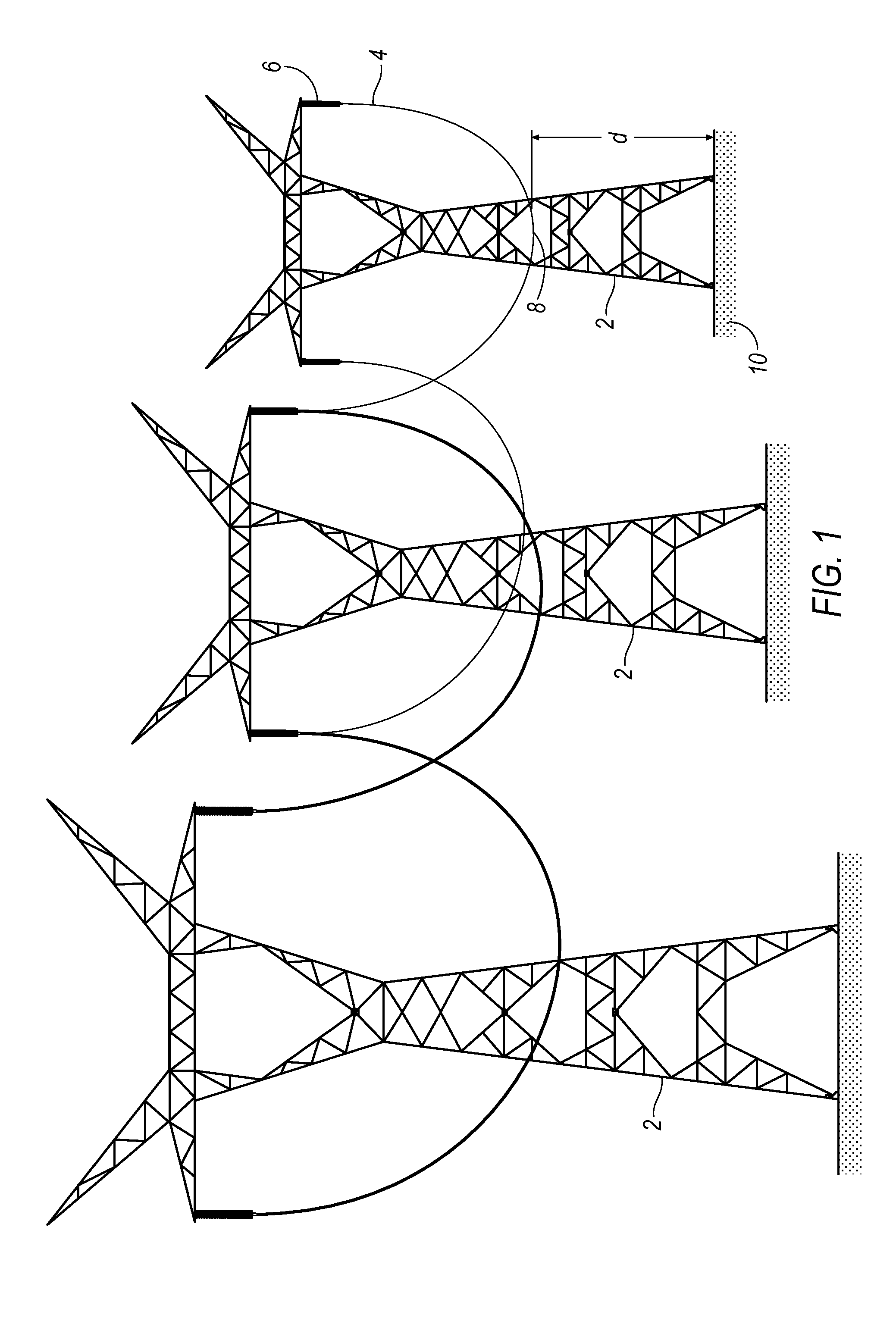
[0036]FIG. 1 illustrates typical transmission lines that one might find in the power grid that is used in our country. High voltage transmission towers 2 traverse our countryside and are connected by transmission lines 4. Insulators 6 suspend the lines 4 from the towers 2. Over time, the distance d between the lowermost point 8 of the power line 4 and the ground 10 will change. FIG. 1 illustrates transmission lines 4 that have aged and are in need of repair.

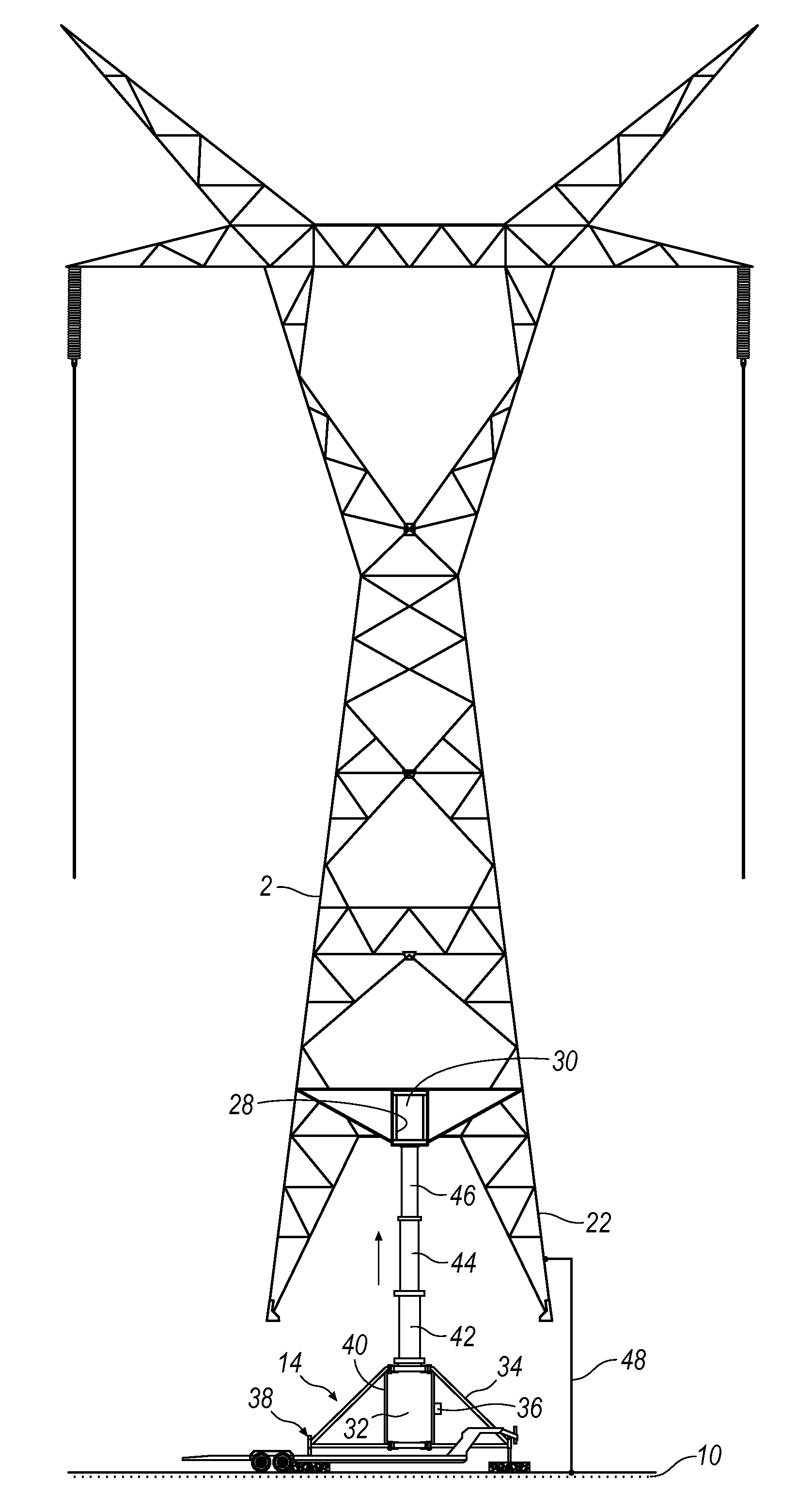
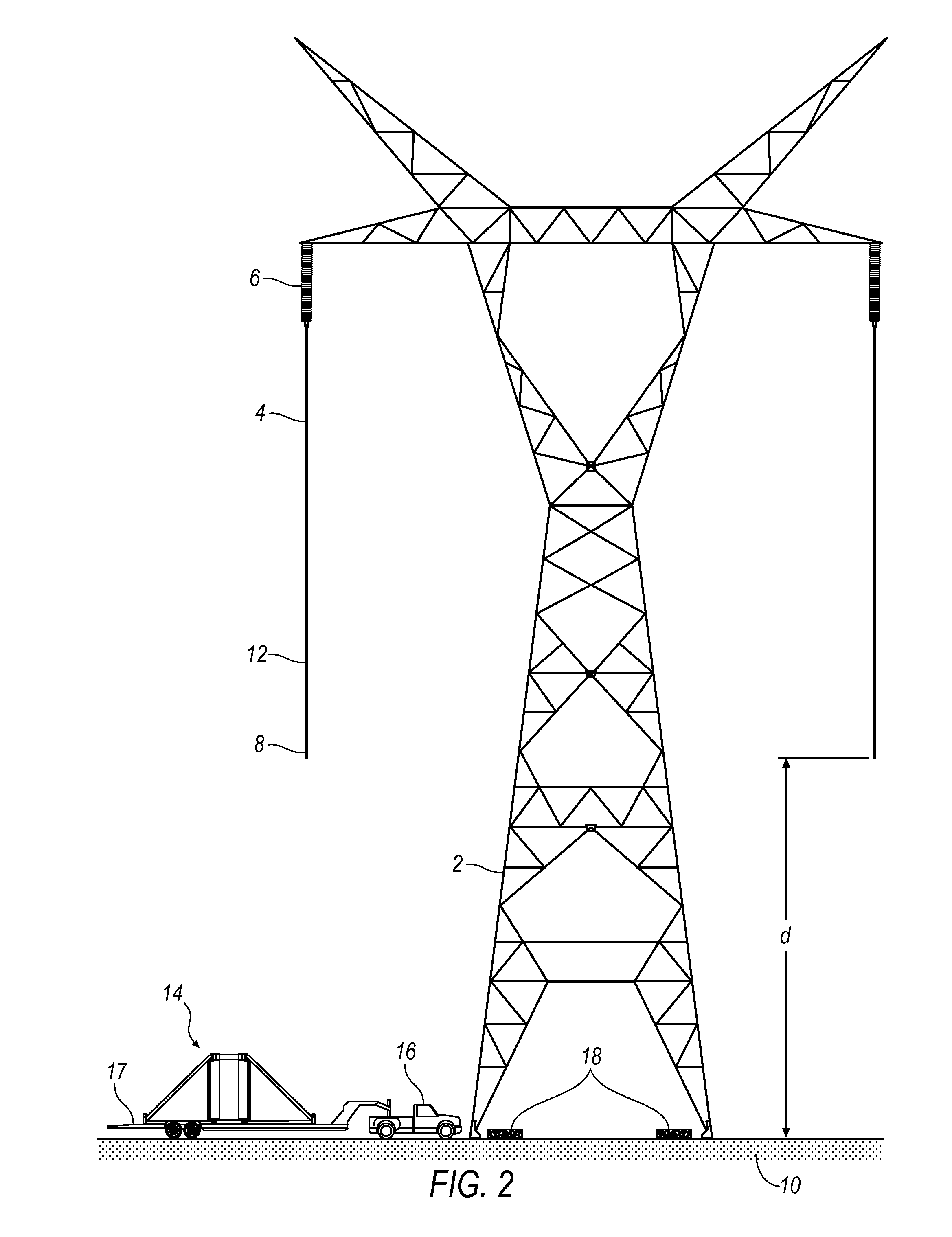
[0037]FIG. 2 illustrates an apparatus and method that can be used to maintain a tower 2 that has transmission lines 4 that have sagged to an unacceptable lower point 8. To address this problem, a novel portable lifting stand system 14 has been delivered to a job site. A vehicle 16 pulls a trailer 17 in place where it can be staged for a maintenance project. The system 14 is transported on the trailer 17. Of course, system 14 could be incorporated into vehicle 16 so the illustrative approach is merely exemplary. The tower is shown...


PUM


Abstract

A tower lifting stand system and method is provided for use in lifting a large structure such as a transmission tower that is used in our power grid. A lifting mechanism engages a structure connected to the tower which work together to lift the tower once the lifting mechanism has been activated. Once the tower is lifted, a vertical extension section can be installed thus lifting the tower, and its associated power lines, vertically a predetermined distance.

Description

CROSS-REFERENCE TO RELATED APPLICATIONS[0001]This application claims priority to U.S. provisional application Ser. No. 61 / 505,703 filed on Jul. 8, 2011, the contents of which are incorporated by reference in their entirety.BACKGROUND AND SUMMARY[0002]Transmission towers are used to provide a mechanism for carrying high voltage power lines throughout an electrical power grid. Typical transmission towers are aligned in a predetermined path and are placed within a power grid in accordance with the needs and demands of a population geographically located within the grid. Over fifty years ago it became customary to erect transmission towers across our country, which in large part have gone unattended and without much maintenance.[0003]Transmission lines are typically secured to the upper portion of transmission towers using insulators, which allow the lines to be stretched from tower to tower. The transmission lines extend for miles and they drape from transmission tower to tower. Over t...

Claims


Application Information

Patent Timeline
Patent Type & Authority Applications(United States)
IPC IPC(8): E04H12/34E04G21/14E04H12/00
CPCE04H12/34E04H12/344
Inventor MARGEVICIUS, JOSEPH R.WASMUND, MARVIN G.OLIVER, ANDREW S.
Owner WALBRIDGE EQUIP INSTALLATION
Why Eureka
Try Eureka