Ultrathin coil tool jig, preparation method and preparation equipment thereof

A technology of tooling fixtures and coils, which is applied in the direction of coil manufacturing, etc., can solve the problems of cost waste, low coil production efficiency, and high manufacturing cost, and achieve the effects of reducing process links, improving production efficiency, and saving equipment costs

Active Publication Date: 2020-04-14
HAITONG COMM ELECTRONICS
View PDF6 Cites 1 Cited by
  • Summary
  • Abstract
  • Description
  • Claims
  • Application Information

AI Technical Summary

Problems solved by technology

[0004] For the implementation of FPC, firstly, the cost of its preparation equipment is high, and secondly, it needs to go through multiple processes such as drilling, copper plating, etching, and covering film, resulting in a high overall defect rate. There are still some bottlenecks in the double-layer thickness process, and the relative manufacturing cost is still relatively high compared with the winding process;
[0005] For the realization of winding, firstly, the production efficiency of the coil is low, and secondly, one tooling jig usually corresponds to one coil product. If multiple coil products need to be produced and processed, multiple sets of coil jigs need to be prepared, which causes Unnecessary waste of cost, and the jig processing cycle is long, and the debugging operation is cumbersome, especially when facing the instability of the coil size and shape of the new project, too many unwinding tooling jigs will increase the cost risk of the project itself, product yield risk;

Method used


Image

  • Ultrathin coil tool jig, preparation method and preparation equipment thereof
  • Ultrathin coil tool jig, preparation method and preparation equipment thereof
  • Ultrathin coil tool jig, preparation method and preparation equipment thereof

Examples


Embodiment 1

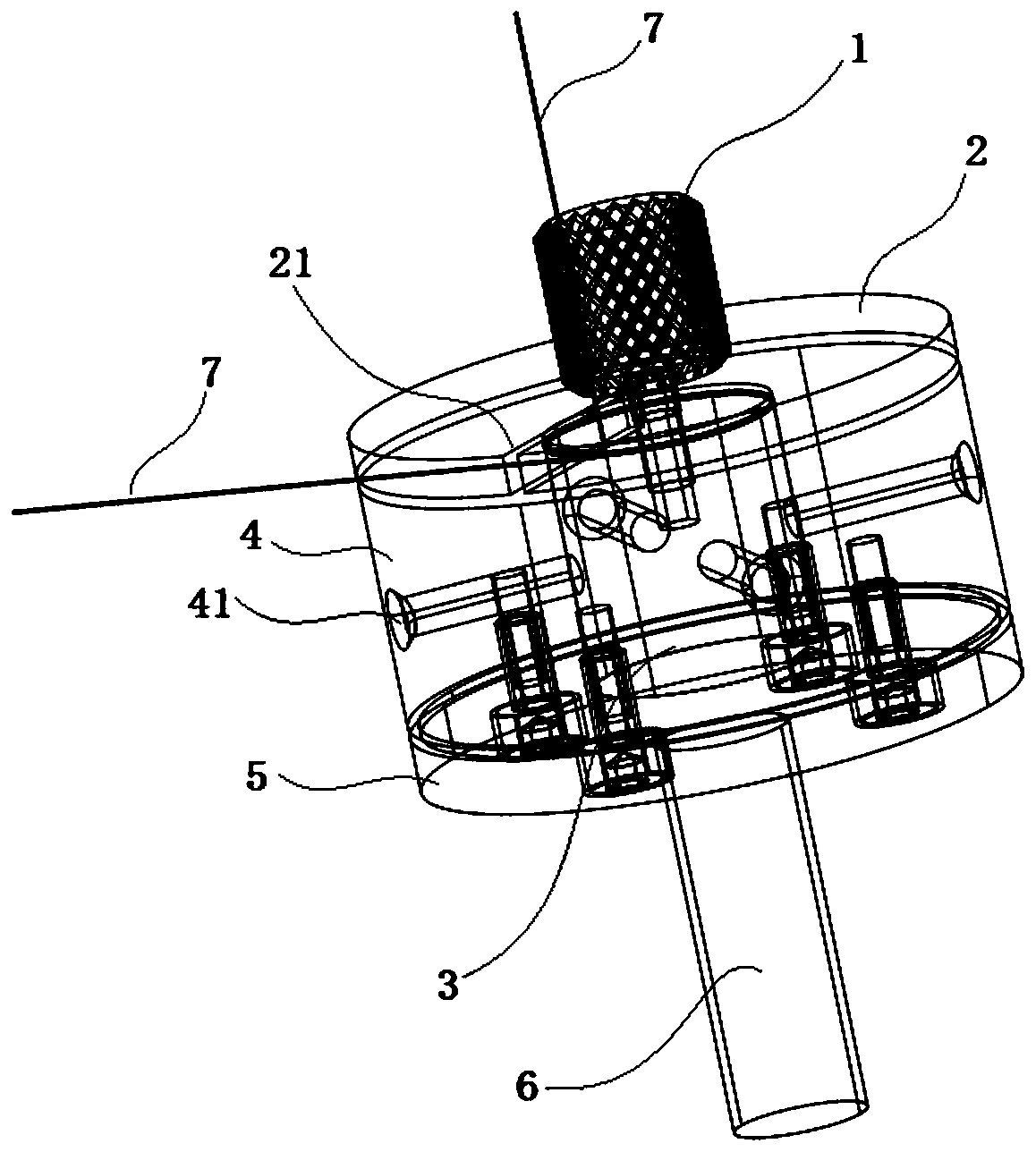
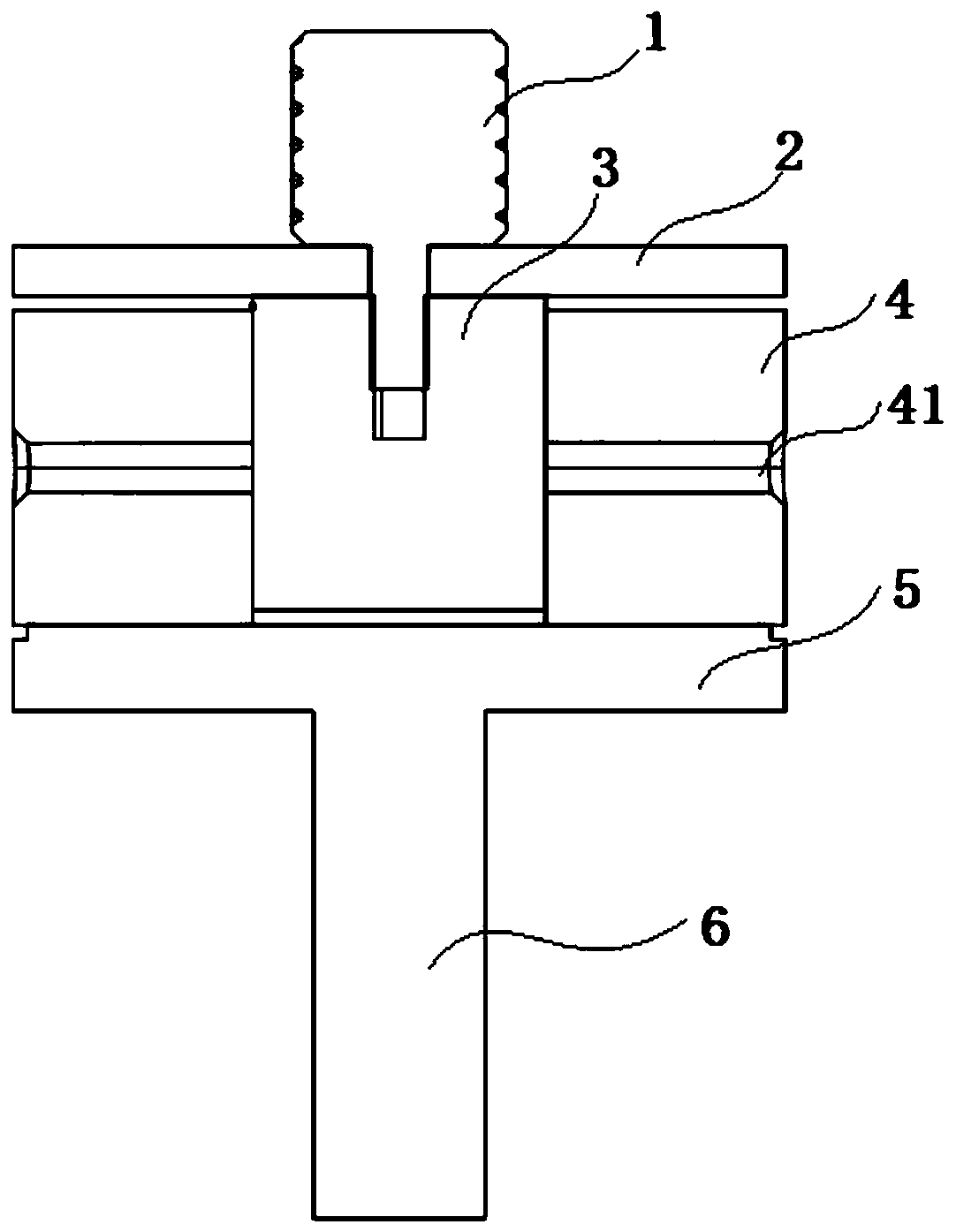
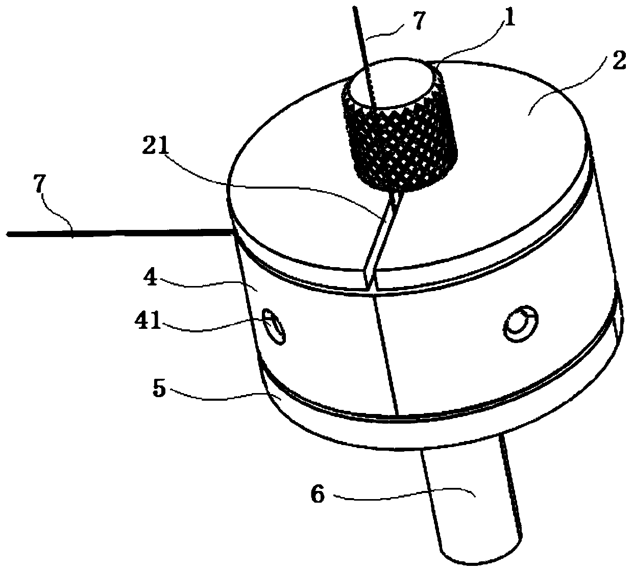
[0048] see figure 1 and figure 2 , the application provides an ultra-thin coil tooling fixture, including: a locking member 1, a cover plate 2, a mold core 3, a mold sleeve 4, a bottom plate 5, and a heat conducting member;

[0049] One end of the locking part 1 passes through the cover plate 2 and is detachably connected to the mold core 3. The mold sleeve 4 is sleeved on the mold core 3. The peripheral side of the mold sleeve 4 is provided with a locking and unlocking mechanism for locking and unlocking the mold sleeve 4 and the mold core 3. The top wire at the middle position, the bottom plate 5 is fixedly connected to the side of the mold case 4 away from the cover plate 2, and the mold core 3 is connected to the external heat source through the heat conducting member; wherein,

[0050] In the coil winding state, the mold cover 4 cooperates with the mold core 3 through the top wire to adjust and lock the distance between the cover plate 2 and the mold cover 4, wherein th...

Embodiment 2

[0063] see Figure 6 , This embodiment provides a method for preparing an ultra-thin coil based on Embodiment 1, using any ultra-thin coil tooling fixture as in Embodiment 1 to prepare the coil, and the method includes the following steps:

[0064] S1: Adjust and lock the distance between the cover plate and the mold sleeve to limit the width of the coil winding;

[0065] S2: Between the cover plate and the mold sleeve, select a single-strand or multi-strand wire to wind the coil around the mold core, wherein, during the coil winding process, the wound coil is heated through the heat conduction of the mold core, so that the coil Adjacent wires are glued to each other;

[0066] S3: After the winding of the coil is completed, unlock the distance between the mold sleeve and the mold core, and press the wound coil by pressing the cover plate and / or the bottom plate, so that the cross-sectional thickness of the wound coil is flat, wherein , During the coil pressing process, the w...

Embodiment 3

[0074] This embodiment provides an ultra-thin coil preparation device based on Embodiment 1, including: any ultra-thin coil tooling fixture in Example 1, and an intelligent numerical control device that cooperates with the tooling tool for coil preparation.

[0075] Due to the ultra-thin coil tooling fixture based on Embodiment 1, the ultra-thin coil preparation equipment of this embodiment has the following technical advantages:

[0076] 1) In this embodiment, the position between the clamping sleeve and the mold core is locked or unlocked by the top screw, so that the distance between the cover plate and the mold sleeve can be changed, and it is suitable for coil wires of different sizes to be wound into coils , realize the purpose of producing multiple coils with one jig, and achieve the technical effect of strong versatility;

[0077]2) In this embodiment, when the jackscrew is locked, the winding groove is formed by the mold core, the mold sleeve, and the cover plate, whi...


PUM


Abstract

The invention discloses an ultra-thin coil tool jig, a preparation method and preparation equipment thereof. The ultra-thin coil tool jig comprises a locking piece, a cover plate, a mold core, a moldsleeve, a bottom plate and a heat conduction piece. One end of the locking piece penetrates through the cover plate to be detachably connected with the mold core, the mold core is sleeved with the mold sleeve, jackscrews used for locking and unlocking the position between the mold sleeve and the mold core are arranged on the peripheral side of the mold sleeve, the bottom plate is fixedly connectedwith the side, away from the cover plate, of the mold sleeve, and the mold core is connected with an external heat source through the heat conduction piece. In the coil winding state, the mold sleeveis matched with the mold core through the jackscrew and used for adjusting and locking the distance between the cover plate and the mold sleeve, the distance between the cover plate and the mold sleeve is the winding breadth of the coil, and the mold core is a winding center shaft of the coil; and in a coil pressing state, the jackscrew is in an unlocked state, and the cover plate and/or the bottom plate are/is a pressing plate used for pressing the wound coil. The method has the technical characteristic of high production efficiency, and the prepared coil has the advantages of small thickness, strong universality, good heat dissipation performance, low cost and the like.

Description

technical field [0001] The invention belongs to the technical field of coil preparation, and in particular relates to an ultra-thin coil tooling fixture, a preparation method and a preparation device. Background technique [0002] With the increasing popularity of smart devices in the market, the charging technology of smart devices has also been continuously developed. Among them, wireless charging has gradually become one of the important charging methods for smart devices. In the field of wireless charging technology, electromagnetic induction wireless charging is a principle of using transformer coupling to couple the coil in the receiver and the coil in the transmitter to realize the function of charging the power supply equipment, and the coil is to realize this kind of One of the core hardware of wireless charging technology. [0003] At present, the production process of wireless charging coil products adopts winding type and FPC to produce and produce: [0004] Fo...

Claims


Application Information

Patent Timeline
Patent Type & Authority Applications(China)
IPC IPC(8): H01F41/04H01F41/06
CPCH01F41/04H01F41/06
Inventor 刘金平杜会亭黄江磊张云龙
Owner HAITONG COMM ELECTRONICS
Why Eureka
Try Eureka