Lamp, battery over-discharge control circuit and method

A technology for controlling circuit and battery voltage, which is applied in the field of lighting, can solve the problems of reducing battery life, reducing life, dim light effect, etc., and achieves the effects of preventing battery over-discharge, long service life and preventing over-discharge

Inactive Publication Date: 2020-04-14
KENNEDE ELECTRIONICS MFG CO LTD
View PDF7 Cites 0 Cited by
  • Summary
  • Abstract
  • Description
  • Claims
  • Application Information

AI Technical Summary

Problems solved by technology

[0002] More and more lamps and lanterns in life are equipped with rechargeable batteries, which makes the use of lamps wider and can be used in places without external power supply. When the lamps are in use, they are powered by batteries. When the battery power is sufficient, the battery remains on Within the higher voltage range, the brightness of the lamp is sufficient; but when the battery power is about to run out, the battery voltage will drop off a cliff, that is, in a short period of time, the voltage value of the battery drop is large, and the lamp’s The brightness will suddenly dim significantly, which will affect the use and cause the user to mistakenly think that the lamp is broken; as the load of the lamp decreases greatly with the battery voltage, the working current will decrease accordingly, so the discharge curve of the battery will decrease gently, but At this time, the luminance produced by the lamp is far lower than the rated state, and the dim light effect is not practical; at the same time, due to the characteristics of the battery, the lower the discharge voltage, the easier it is to reduce the service life of the battery. Therefore, it is necessary to design a new type Advanced battery over-discharge processing circuit and method to prevent battery over-discharge from reducing life, and reasonably control the load current of the lamp to ensure the practicability of the brightness of the lamp under the full use state

Method used


Image

  • Lamp, battery over-discharge control circuit and method
  • Lamp, battery over-discharge control circuit and method
  • Lamp, battery over-discharge control circuit and method

Examples


Embodiment Construction

[0027] Embodiments of the present invention are described in detail below, and examples of the embodiments are shown in the drawings, wherein the same or similar reference numerals denote the same or similar elements or elements having the same or similar functions throughout. The embodiments described below by referring to the figures are exemplary only for explaining the present invention and should not be construed as limiting the present invention.

[0028] In the description of the present invention, unless otherwise clearly defined, words such as setting, installation, connection, and fixing should be understood in a broad sense, and those skilled in the art can reasonably determine the specific meanings of the above words in the present invention in combination with the specific content of the technical solution .

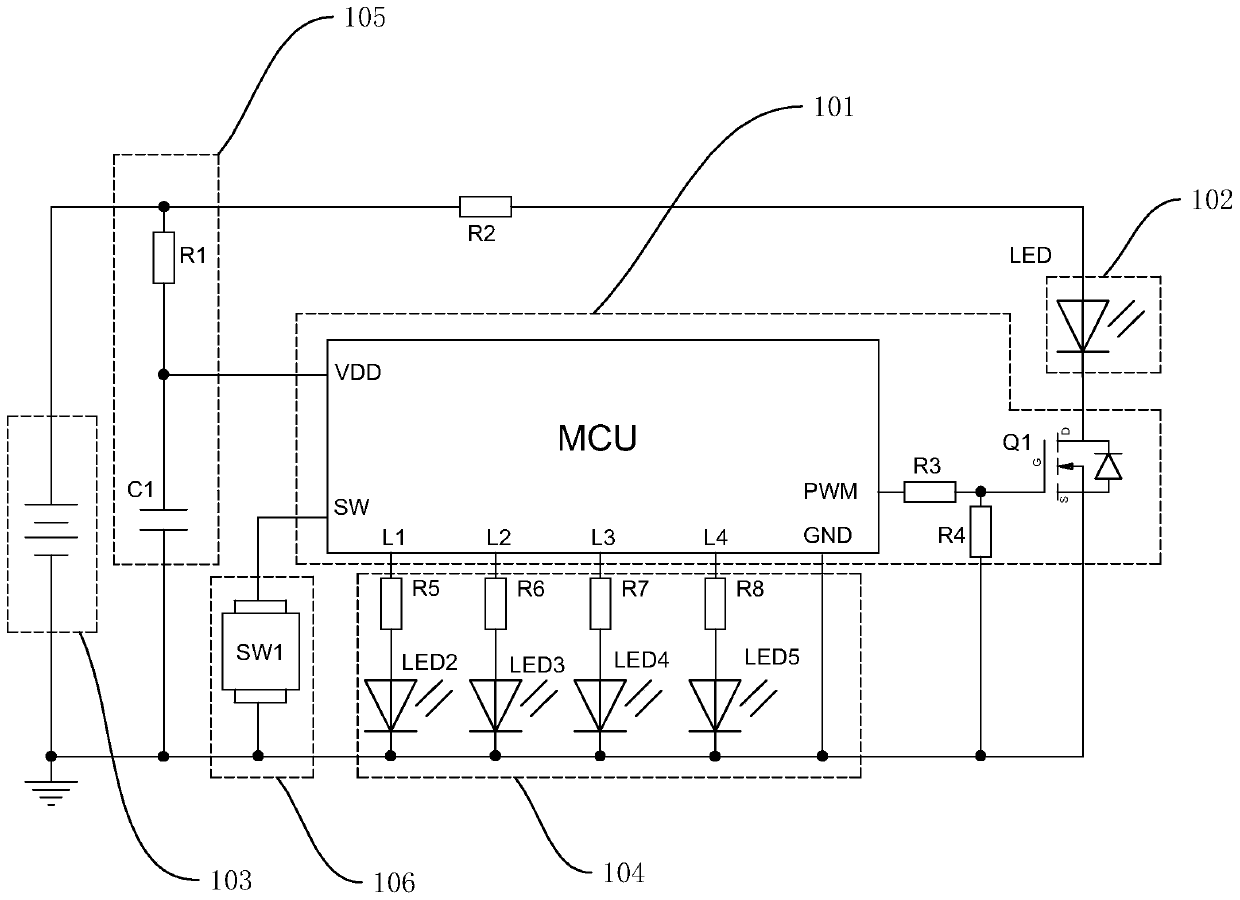
[0029] refer to image 3, a battery over-discharge control circuit in one embodiment of the present invention includes a battery module 103 to provide powe...


PUM


Abstract

The invention discloses a lamp and a battery over-discharge control circuit and method. The method comprises the steps: judging whether a voltage of a battery is reduced to an over-discharge state ornot through detecting the voltage of the battery, and reducing a current of a load when an electric quantity of the battery is consumed and enters an over-discharge state so that the voltage of the battery rises again; when the electric quantity of the battery is continuously consumed, reducing the voltage to the over-discharge state again, and reducing the current of the load again so that the voltage of the battery rises again; and after repeated and stepped reduction of the load current for multiple times, keeping the battery voltage in a state above the over-discharge state, and when the load current is reduced to a preset current value, if the current is reduced again, and brightness emitted by the load is too dark and has no practical significance, turning off the power supply. By using the method, the battery can be effectively protected, over-discharge is prevented, and meanwhile a situation that when the lamp is in a bright use state, due to over-discharge of the battery, thebrightness is suddenly and greatly reduced, and the lamp is in an unpractical state of being too dark and incapable of lighting is avoided.

Description

technical field [0001] The invention relates to the lighting field, in particular to a lamp and a battery over-discharge control circuit and method. Background technique [0002] More and more lamps and lanterns in life are equipped with rechargeable batteries, which makes the use of lamps wider and can be used in places without external power supply. When the lamps are in use, they are powered by batteries. When the battery power is sufficient, the battery remains on Within the higher voltage range, the brightness of the lamp is sufficient; but when the battery power is about to run out, the battery voltage will drop off a cliff, that is, in a short period of time, the voltage value of the battery drop is large, and the lamp’s The brightness will suddenly dim significantly, which will affect the use and cause the user to mistakenly think that the lamp is broken; as the load of the lamp decreases greatly with the battery voltage, the working current will decrease accordingly...

Claims


Application Information

Patent Timeline
Patent Type & Authority Applications(China)
IPC IPC(8): H02J7/00H05B45/10H05B45/50
CPCH02J7/0029H02J7/0031H05B44/00Y02B20/30
Inventor 黄植富林铁英
Owner KENNEDE ELECTRIONICS MFG CO LTD
Why Eureka
Try Eureka