Automatic production equipment for electronic components
An electronic component and automatic production technology, applied in the field of automation, can solve problems such as inconsistency in bending effect angles, high risk, and high manual labor intensity, and achieve detection and positioning accuracy and detection efficiency. The effect of product quality and convenient operation
- Summary
- Abstract
- Description
- Claims
- Application Information
AI Technical Summary
Problems solved by technology
Method used
Image

Examples
Embodiment 1
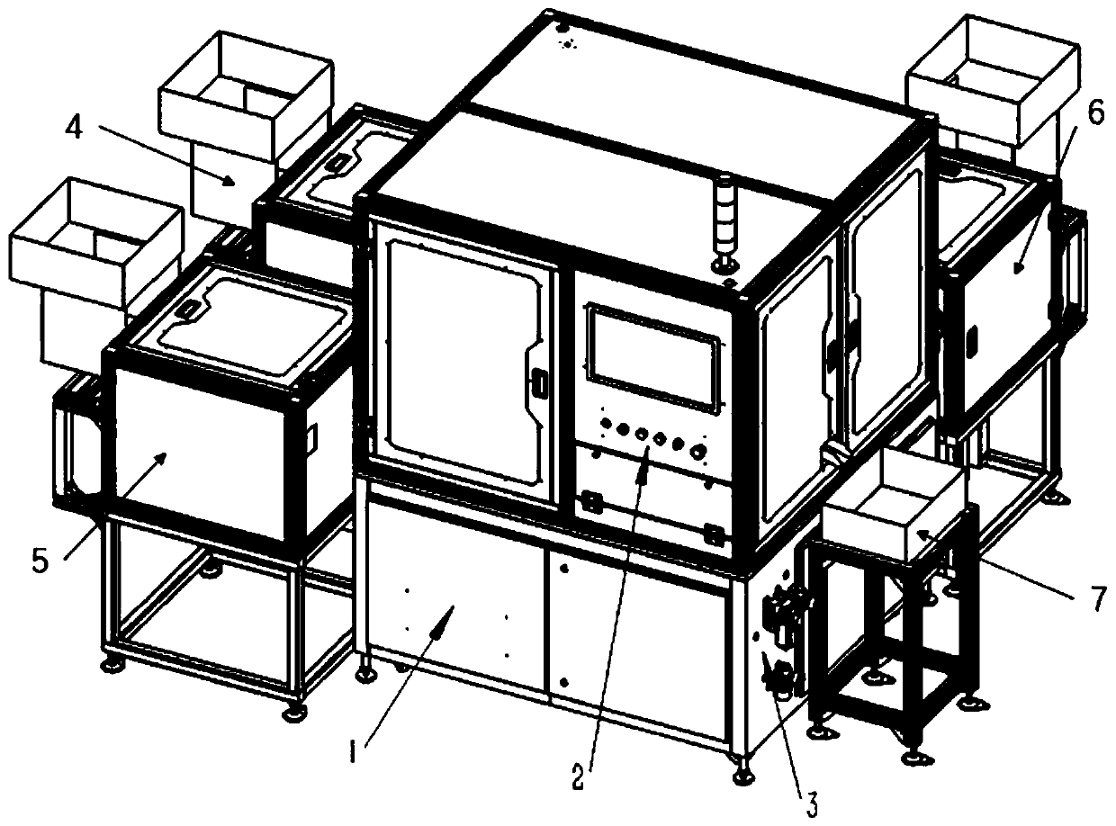
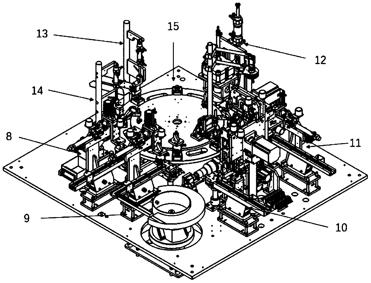
[0026] Embodiment 1: see figure 1 , figure 2 , image 3 , Figure 10 , Figure 11 , Figure 12 , an automatic production equipment for electronic components, including an electric control box 1, an operation panel 2, a pneumatic control assembly 3, a base loading assembly 6, an inner claw loading assembly 4, an end cover loading assembly 5, and a feeding box 7. The electric control box 1 and the operation panel 2 are respectively placed on the upper and lower sides of the installation base plate 15, and the inner jaw feeding assembly 4, the end cover feeding assembly 5, the base feeding assembly 6 and the unloading box 7 are respectively located on the installation Around the bottom plate 15, the inner claw feeding assembly 4, the end cover feeding assembly 5 and the base feeding assembly 6 have similar structures, which are collectively referred to as the external vibrating plate mechanism 122 here, and all include a feed bin 120, a material guide plate 121, Sound insul...
Embodiment 2
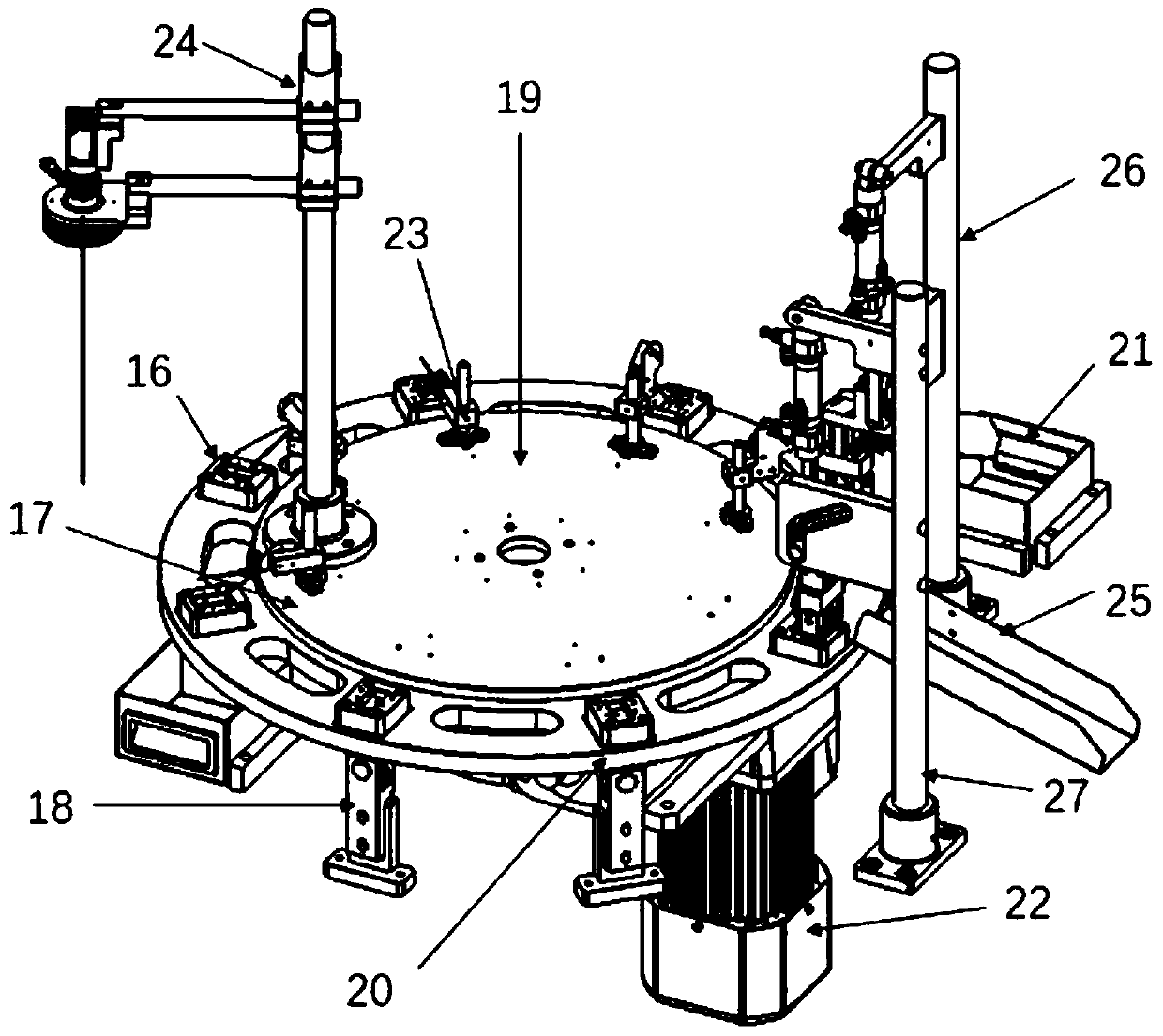
[0027] Example 2: see figure 2 , image 3 , Figure 4 , an automatic production equipment for electronic components provided by the present invention will now be described. The base feeding mechanism 8 is distributed outside the index plate mechanism 19, and the base feeding direct vibration feeding plate 31 is connected to the base feeding assembly 6. , the base feeding horizontal push cylinder 28 in the base feeding mechanism 8 is fixed on the base feeding support seat 29, and is connected with the base feeding vertical pull-down cylinder 34 through the base vertical fixing block 35, and the base is vertically fixed The bottom of the block 35 is provided with a base feeding jaw cylinder 36, and the base feeding jaw cylinder 36 is connected with a base feeding jaw 37, and the base feeding support seat 29 is provided with a base feeding direct vibration feeding plate 31 in a parallel direction. A base straight channel sensor 30 is fixed above the base feeding straight vibra...
Embodiment 3
[0028] Embodiment 3: see figure 2 , image 3 , Figure 5 , the automatic production equipment of a kind of electronic components and parts provided by the present invention is described now, and described washer feeding mechanism 9 is distributed on the outer side of index plate mechanism 19, and washer feeding direct vibrating feeding plate 54 and washer feeding and discharging plate 44 are vertically docked, the washer feeding and discharging plate 44 is fixed on the discharge port of the washer vibrating plate 45, the washer vibrating plate 45 is fixed on the washer vibrating plate base 46, and the washer vibrating plate base 46 is fixed on the installation base plate 15, The gasket feeding horizontal push cylinder 41 in the gasket feeding mechanism 9 is fixed on the gasket feeding support seat 42, and is connected with the gasket feeding vertical pull-down cylinder 47 through the gasket vertical fixing block 48, and the gasket vertical fixing block The bottom of 48 is p...
PUM
 Abstract
Description
Claims
Application Information
 - R&D
- Intellectual Property
- Life Sciences
- Materials
- Tech Scout
- Unparalleled Data Quality
- Higher Quality Content
- 60% Fewer Hallucinations
Browse by: Latest US Patents, China's latest patents, Technical Efficacy Thesaurus, Application Domain, Technology Topic, Popular Technical Reports.
© 2025 PatSnap. All rights reserved.Legal|Privacy policy|Modern Slavery Act Transparency Statement|Sitemap|About US| Contact US: help@patsnap.com